VAC Sigma 170i iQ Integrated Amplifier Instruction

SAFETY NOTICES, WARNINGS, AND CAUTIONS
The MAINS plug is used as the disconnect device. Disconnect the mains plug from the apparatus before servicing the unit.
Operate only from an AC MAINS SUPPLY of the voltage indicated. If voltage conversion is necessary it must be done at the VAC factory or by the importer.
The MAINS SUPPLY must be EARTHED (GROUNDED). Do not defeat or remove the MAINS cord safety ground connection. Do not connect the mains cord to an outlet that is not properly earthed.
Provide adequate ventilation – allow at least 5 inches above, to each side, and to the rear.
Do not place in a completely enclosed cabinet.
Do not stack other equipment on top of the VAC unit.
Do not operate on carpet or any other surface that might block air flow. Do not impede air flow.
Keep all flammable objects away from the amplifier.
No naked flame sources should be placed on or near the apparatus.
Do not leave the apparatus unattended in operation.
Apparatus must not be exposed to dripping or splashing. Do not place objects filled with liquids on the apparatus.
This apparatus is heavy. Be certain to install it in a secure location from which it can not fall or tip over. Obtain appropriate assistance to unpack, move, and install the apparatus.
Never operate the apparatus without all covers and cages securely in place.
Vacuum tubes become hot enough to cause serious burns. Never touch a tube when the apparatus is on; it may take several minutes for it to cool down after the apparatus is switched off.
Do not touch a tube if the glass is broken; the internal structure carries high voltage. Unplug the apparatus and wait 30 minutes before attempting to remove such a tube.
INSTALLING THE TUBES
The Sigma 170i iQ is shipped with the vacuum tubes removed.
The large tubes (type KT88) have a plastic center pin, called a “keyway”, that can only be inserted one way. Do not to break this pin!
The small tubes have a gap in the pins that matches the sockets, and they can only be inserted one way.
There are markings on the base or bottom of each tube that corresponds to each socket on the amplifier; place the tubes in the indicated sockets.
FUSE
It is unlikely that you will ever need to change a fuse.
The fuse is located in a small drawer that is built into the AC power receptacle. There are two possible positions in the drawer. The one nearest to the inside of the chassis is the active fuse. The position nearer to the outside of the chassis may be used to store a spare fuse.
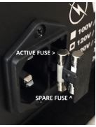
Adjacent to the fuse holder you will find text indicating the operating voltage for your amplifier and the appropriate fuse rating. Fuses of are the Sx20mm size and should be of the “T” ( “slow blow” or “time delay” type).
Use only fuses that have the proper safety approvals for your country.
INSTALLATION
- Provide adequate ventilation. Do not operate on carpet or any other surface that might block air flow. Allow at least 5 inches of free space above, to each side, and behind the amplifier.
- The chassis will become warm in normal use.
- Do not allow the chassis to touch any metal parts, such as the frame of an equipment rack.
This might create a parallel ground path that could degrade the sound. - Input connection is via single ended RCA jacks.
- The optional balanced input via XLR jacks connects to Input 4.
- Preamplifier output is on RCA.
- Connect line level inputs (CD, Tuner, Tape, etc.) to the appropriate RCA or XLR input jacks on the rear panel. Note: with the exception of Phono all inputs are “line level”
- The optional phono input appears on Input 1. Connect phono cables to the rear panel Input 1. Connect the shield wire(s) from the turntable(s) or phono cable(s) to the chassis connection terminal provided on the rear panel.
- Connect the speaker cables to the terminals that match the nominal or minimum impedance of your loudspeakers (you may try all of them). Do not operate the amplifier
without loads. Please note that because the line stage inverts absolute phase, you should connect the RED terminal of your loudspeakers to the COMMON terminal of the Sigma. - Do not remove and connect input cables or speaker cables while is amplifier is running. Doing so risks damage to your loudspeakers or the amplifier.
- Connect the power supply to the power source indicated on the rear panel, either 100, 120, 220, or 230/240 volts AC. The power source must have an earthed (grounded) connection. Avoid power conditioners that float the ground pin. For best performance, try to route the power cord away from signal cables.
- Pay close attention to power quality, and be aware that different power cords can alter the sound.
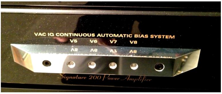
- The KT88 output tubes are automatically biased by the patented VAC iQ circuit. Any fault will be indicated by one of four lights in the silver bar on the front panel. See INSTALLING NEW OUTPUT TUBES and VAC iQ SYSTEM.
INPUTS (back panel)
Pairs of RCA jacks accommodate unbalanced line level sources.
The optional phono stage is fitted to Input 1.
When fitted, the XLR input can accept a balanced or unbalanced line level source and is routed to the Input 4 position of the SELECTOR switch.
Note: not all sources with XLR connectors are balanced. Many are unbalanced, with pin 2 or pin 3 tied to ground. The Sigma 170i iQ will accept such sources. XLR Pin 2 has the same polarity as the RCA inputs.
The “CINEMA” inputs accept an unbalanced line level source via RCA jacks. The VOLUME control does not effect the level of the CINEMA input
PREAMPLIFIER OUTPUTS
RCA output jacks are provided as main preamplifier outputs; these may be used, for example, to drive an additional power amplifier, subwoofer, or to insert an external crossover (in conjunction with the Cinema input).
OPERATION
Turn the “Volume” control fully counter clockwise.
As with all high fidelity products, the sound characteristic of the VAC changes somewhat as it warms up. Best sound will be achieved after about 15 minutes of operation.
Any time that the Sigma 170i iQ has not been used for a few weeks the sound may be different.
This is also normal for high resolution audio equipment. Optimum sound should return after a few hours of operation, preferably with an audio signal.
Note that although your VAC System has been run for 48 hours at the factory, it will continue to “break in” for approximately 200 hours. Also be aware that many components display the need for a new break in period after being transported in unheated cargo aircraft.
FUSES
There is a main fuse located in the IEC AC power inlet; there is also a spare fuse included.
For 220 or 240 volt operation, please use a 2.5 ampere fuse, Sx20mm, type “T” (slow blow/time delay).
REMOTE CONTROL
The remote control allows for wireless adjustment of VOLUME and MUTE.
The remote wand is powered by two “AAA” batteries. These should be of the alkaline type. You will need to install them in the wand before using the remote. Since batteries can leak, they should be removed from the wand if it is not going to be used for an extended period of time.
FRONT PANEL CONTROLS
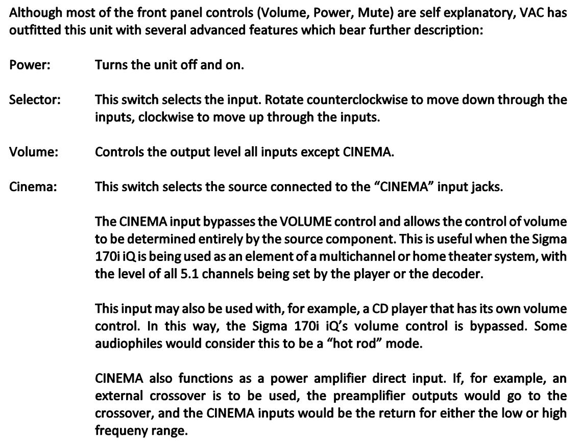
TOP CONTROLS- OPTIONAL PHONO STAGE
MODE: MM (38 dB gain) or MC (58 dB gain) settings.
MC Ohms: Three positions for three possible MC resistive load settings (values marked). Does not effect the MM mode.
REPLACEMENT OF TUBES
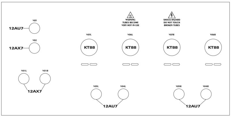
V0lL, V0lR 12AX7 /ECC83 (low noise tested)
V02 12AX7 /ECC83
V03,V04L,V04R,V0SL,V0SR 12AU7 /6189/ECC82
V06L,V06R,V07L,V07R KT88
We recommend that you use only tubes specifically selected and tested by VAC for this application.
Before replacing tubes, all power must be turned off. Allow 15 minutes for the tubes to cool down before touching them – in use they become hot enough to cause burns.
Install new tubes of the appropriate types firmly in their sockets, noting the location of holes in the socket and pins of the tubes, taking care to make sure that pin pattern corresponds to holes in tube socket (12AX7 and 12AU7) or the center key (KT88).
The patented VAC iQ circuit automatically adjusts the KT88 operating settings. See VAC iQ SYSTEM.
In the event that trouble is encountered, check all signal, speaker and power connections. If the problem persists, follow all safety precautions stated earlier in this section, and check that all tubes are correctly seated in their sockets. If possible, try another tube. If the problem persists, please consult your VAC dealer or contact the factory directly.
Tubes are like the tires on a car; they will eventually need replacement. Murphy’s Law states that a tube will probably fail right at the start of a long holiday weekend. Therefore, many audiophiles keep a spare tube of each type on hand, just in case!
VAC can test tubes for concerned customers.
INSTALLING NEW OUTPUT TUBES
Output tubes are type KT88. Replacement output tubes should be purchased from VAC. It is desirable that tubes be in matched quartets, and be close to the “bogey” values for the major parameters. Make certain that each tube fits firmly in its socket.
ALL POWER MUST BE OFF. Wait 15 minutes for the old tubes to cool down (THE TUBES BECOME HOT ENOUGH TO CAUSE SERIOUS BURNS WHEN IN OPERATION AND MAY TAKE SEVERAL MINUTES TO COOL DOWN). Install the new tubes firmly and fully in the sockets, observing that the tube will only fit into the socket in one orientation, determined by the plastic “keyway” in the center of the base. Do not use excessive force.
No adjustment is necessary. The patented VAC iQ circuit continuously keeps the KT88 tubes at the optimal setting.
A slight blue glow in the tube is not cause for concern. If at any time the plate (the outermost metal structure) of the output tubes begins to glow bright orange or red SWITCH OFF IMMEDIATELY. The red glow indicates that the tube is “running away”, being destroyed by conducting excessive current. Tubes may run away for several reasons:
In the event that trouble is encountered check connections and/or try another tube. Stop if the problem persists and consult with your dealer or VAC.
For further information, refer to Tips & Advice: Tubes in General and Tips & Advice: Output Tubes.
The VAC iQ System
In engineering, the abbreviation “lq” denotes the quiescent current of a vacuum tube, also known as the idle current or bias point. The lq is what is being set when you adjust an amplifier’s bias.
For best performance, the idle current must be set and maintained precisely, even as the amplifier warms up, the power line varies, the tubes drift, and regardless of whether you’re playing the music softly or loudly. No system has been able to do this. Until now.
The result of 25 years of research, the patented VAC iQ Bias Control System is the only system able to monitor continuously the true quiescent current point of each output tube and hold it precisely at the desired value, thus ensuring optimal performance at all times. It actually outperforms manual systems because it can correct for the heating effects that occur when reproducing loud passages of music. The VAC circuit both MONITORS and CONTROLS, continuously, in real time.
The resulting performance difference is one that you can easily hear. And not only does it sound better, it radically reduces the rate of tube failures, and is self-diagnosing.
In operation:
The iQ circuit monitors and maintains the correct bias adjustment for the KT88 output tubes at all times, regardless of the music playing. It also contains two other components that inform you of tube condition and protect the amplifier; the operation of these two circuits is indicated by the bicolor LEDs located in the silver trim bar on the front of the amplifier.
If an LED illuminates GREEN. this is an indication that the associated KT88 is becoming weak. In a conventional amplifier, you would have advanced the bias control well clockwise for this tube. No immediate action is required; simply replace this KT88 with a fresh one when time permits, and the amplifier will make the best of the weak tube until then.
An LED will illuminate RED if an output tube draws excessive current, i.e., if a ‘run away’ occurs. Because of the stabilizing action of the auto bias circuit, this is most likely to occur if something inside the tube has physically broken. The iQ system detects the fault within a fraction of a second and shuts down the main power supply, thus preventing any damage; all of this happens long before the fuse can react . Switch power off, and replace and discard the indicated tube after it cools down.
CARE OF CHASSIS
VAC chassis are aluminum for superior electromagnetic performance. The main chassis is finished in a durable powder coat paint. Cleaning the units with a damp cloth WHILE THE AMP IS SWITCHED OFF AND UNPLUGGED should suffice. Do not get cleaning solutions onto or into the tube sockets.
The fascia is a multistage gloss lacquer, which may be treated as you would a fine automotive finish.
TIPS & ADVICE SECTION
A Word About Tubes in General
Each brand of tube can sound different in a particular high resolution circuit, because no two manufacturers make a tube type in quite the same way, and the central tendencies of the performance parameters will differ. To emphasize the point, examine the plate structure of 6SN7’s from different manufacturers and you may find that they are not even the same shape and size. (Be careful here, as often a tube is made by a firm other than indicated on its label. In the heyday of tubes it was common to cross brand between major labels. Today many labels do not manufacture their tubes at all, including Gold Aero and RAM.)
This sonic variability may at first seem a liability, but further thought will reveal that it is an advantage, just like the ability to adjust VTA on a tone arm. The owner of a tube amplifier can select tubes which sound like the real thing in his/her specific system. Of course, if the manufacturer you prefer is rare you may want to purchase a few spare tubes for the future.
How long should tubes last? It has long been known in professional circles (and probably now forgotten) that a tube such as the 12AX7 will display better performance characteristics after two years of continual operation than when it was new. In normal use it is not unusual for a low level tube to last 5 years or longer. Output tubes are another story, as they are continually providing significant amounts of current. Here the sound is your best guide. Certainly a tube should be replaced when its emission is significantly down or its transconductance is substantially out of specification. In normal use, output tubes will last at least 2 years and perhaps more than 5 years.
In the event of unusual noise in one channel, or a loss of sound in one channel, some steps may help you locate a bad tube.
For phono only noise, start by exchanging V0ll with V0lR; if the problem changes channels then you have found the bad tube.
Non-phono noise that stops when the unit is muted will be either V02 or V03 (probably V03).
For noise that persists even when the unit is muted, perform a series of pair-wise exchanges, V04L with V04R, V0SL with V0SR, VOGL with V06R, and V07L with V07R. When the problem is observed to have moved to the other speaker, you know you have identified the problematic tube.
VAC can test tubes for concerned customers.
Tips: Output Tubes
Your VAC Amplifier uses the KT88 kinkless tetrode. It is strongly recommended that replacement tubes be purchased only from VAC. If, however, you want to customize the sound to your tastes, be aware that as with interconnects and speaker cables, each tube manufacturer’s KT88 tends to have a distinct sound, as well as its own reliability profile.
You may also use type KT90, KT99a, KT120, and KT150.
Tips: Impedance Matching
We strongly suggest that you experiment with the available impedance connections for the best sonic match with your system. Since no loudspeaker represents an unchanging impedance at all frequencies, it is impossible to assert with certainty which output tap is appropriate to use. In many systems an amazing difference in sound will exist between the various impedance taps.
Since the impedance of most loudspeakers vary over a wide range experimentation is essential. Most speakers have a rated impedance of 4 or 8 ohms. We recommend starting with the 4 ohm connection; after you know the sound if that connection, try the alternatives. Choose the connection that sounds best to your ears.
“2-4” taps generally are best for 4 ohm speakers
“4-8” taps generally are best for 8 ohm speakers
“8-16” taps generally are best for 16 ohm speakers
REGISTRATION FORM
Your equipment is warranted for a period of thirty (30) days from the date of purchase. In addition, if the registration form is received by VAC along with a copy of your sales receipt from an authorized VAC dealer within this thirty days, a service contract will be extended to cover your equipment for two (2) years (tubes excepted). This warranty applies only to units sold in the United States of America through authorized VAC dealers and operated in the USA by the original owner. It covers factory service and, within the continental U.S., standard return shipping. For warranty information outside of the U.S. contact the importer of VAC equipment for your country. Units sold outside of the U.S. should still be registered with VAC. It is responsibility of the dealer and customer to determine suitability of this unit for a given application.
Your questions and comments are always welcome. Contact:
Valve Amplification Company
2172 10th Street
Sarasota, FL 34237
Telephone (941) 952-9695 Fax (941) 952-9691 info@vac-amps.com
_____________ Detach and mail to the address above as soon as possible. ___________
Sigma 170i iQ Integrated Amplifier Registration Form

