User Manual of LOCINOX
SlimStone-2 keypad
![]() COPYRIGHT
COPYRIGHT
Copyright© 2019 Locinox. All rights reserved. This product incorporates copyright protected technology that is protected by a number of EU patent method claims and other intellectual property rights owned by the Locinox Corporation and other rightholders.
Use of this copyright protected technology must be authorized by the Locinox Corporation. Reverse engineering or disassembly is prohibited.
No part of this publication can either be reproduced, communicated, transcribed, stored in a retrieval system or be translated into any language in any form or by any means, whether electronic, mechanical, magnetic, optical, chemical, manual or otherwise, unless explicit written consent has been given by the copyright holder.
![]() NOTICE
NOTICE
The contents of this publication are subject to change. The Locinox Corporation reserves the right to alter the contents of this publication at any time and without notice. The contents of this publication may contain inaccuracies or typographical errors and is supplied for informational use only
![]() TECHNICAL SUPPORT
TECHNICAL SUPPORT
If you require any additional information or assistance during the installation, please contact your dealer, who will be able to provide the latest information. Alternatively, you can visit the Locinox website for more technical information or e-mail us on locinox@locinox.com. Please keep the serial number at hand of your product for future support.
SlimStone-2
MANUAL
SlimStone-2
Congratulations with the purchase of your SlimStone-2
PRODUCT DESCRIPTION
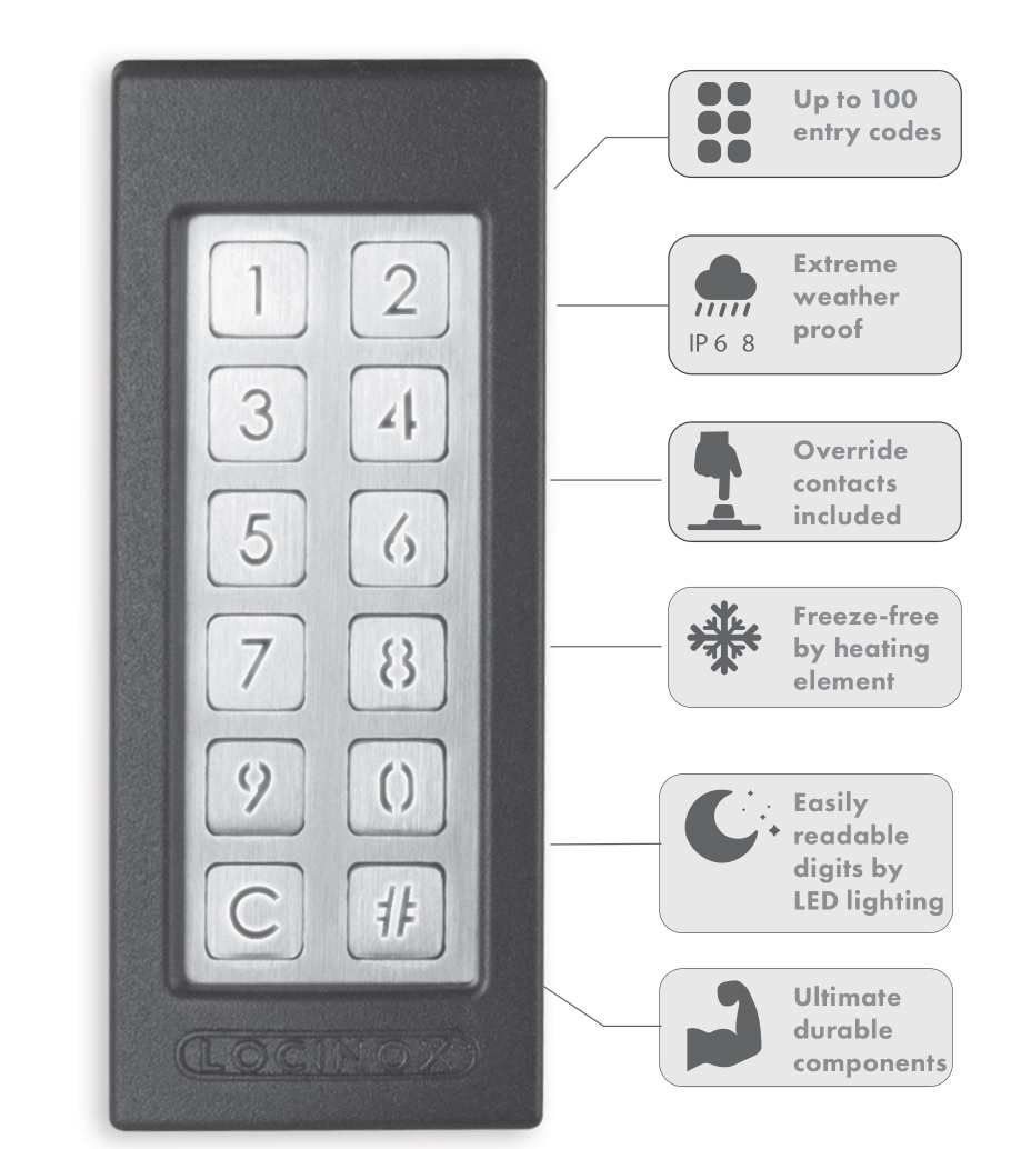
The SlimStone-2 is a sturdy, weather resistant keypad with integrated LED lighting. This keypad is unique in its kind thanks to its durability.
Developed and tested for use in the most extreme weather conditions, SlimStone-2 guarantees access control in all circumstances.
Thanks to the 2 integrated relays, with normally open and normally closed contacts, both the coupling to Locinox and other automation
products and the programming of the SlimStone-2 are very easy. Equipped with innovative QuickFix, alternative fixings for wood and stone are also supplied.
The SlimStone-2 is made of an aluminium powder coated housing with a brushed stainless steel key panel and ditto push buttons.
Up to 100 codes can be programmed.
TECHNICAL SPECIFICATIONS

![]() Under -20°C/-4°F a 24V power supply is recommended.
Under -20°C/-4°F a 24V power supply is recommended.
MOUNTING
STEP 1
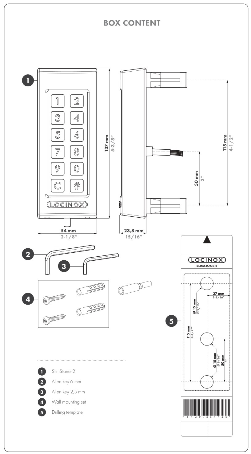
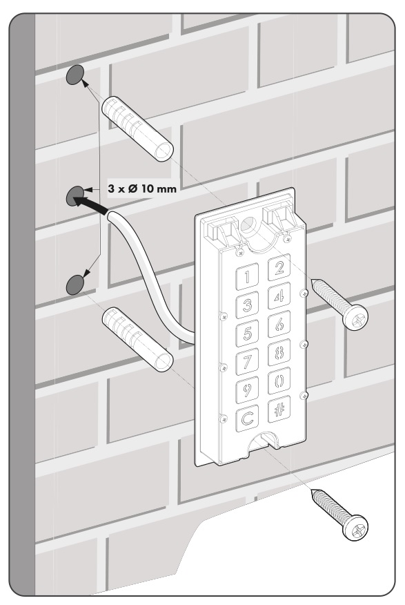
Stick the template and drill into the wall or post (see p.5).

STEP 2
Remove the cover of the SlimStone-2.

STEP 3A
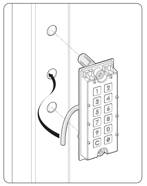
Run the cable through the middle hole in the post.
STEP 4
Position the SlimStone-2 and tighten both Quick-Fix.

STEP 3B
Run the cable through the middle hole in the wall.
STEP 5
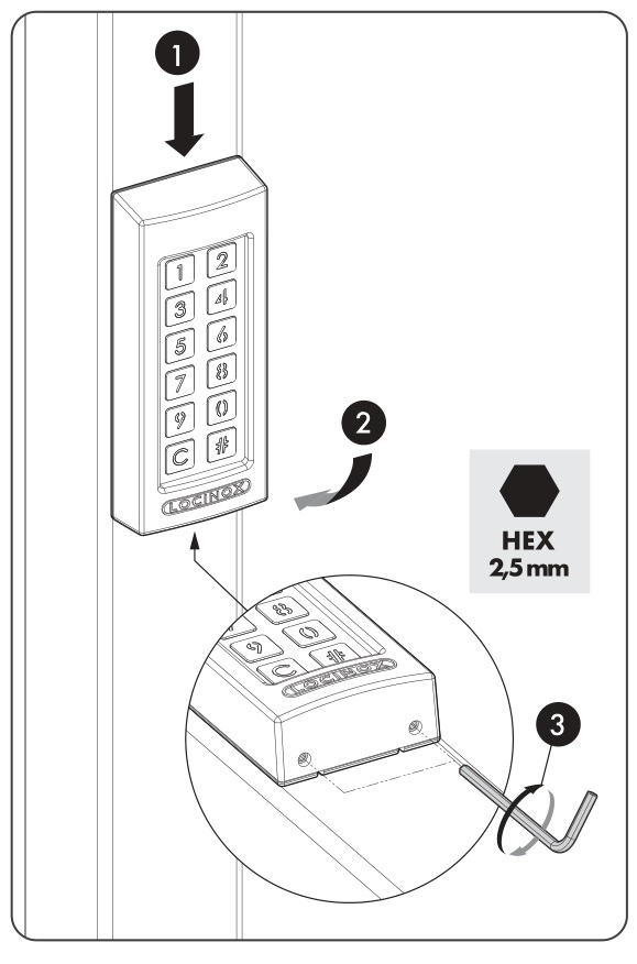
Position the cover and tighten using 2 screws underneath.
CABLING
The SlimStone-2 is equipped with a 2 m long 10 conductor cable.
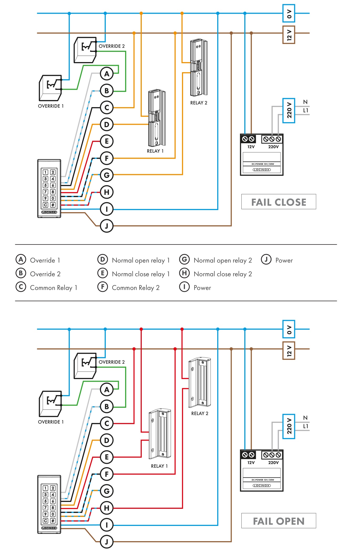
See p. 118 for a detailed connection scheme.
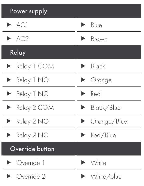
![]() Unused cable ends must be insulated separately to ensure a proper functioning of the keypad.
Unused cable ends must be insulated separately to ensure a proper functioning of the keypad.
CONTROL INPUTS
- You can connect an external button or actuator that will activate the relays and have priority over PIN code. For example, using an intercom or free exit.
- To activate the first relay, connect the NO contact of the external button for relay 1 between J (override 1) and the 0V line (in case of DC), or one of the power lines (in case of AC).
- To activate the second relay, connect the NO contact of the external button for relay 2 between I (override 2) and the 0V line (in case of DC), or one of the power lines (in case of AC).
- For more details on control inputs, see the scheme on page 63
 Attention! This must be a dry contact with NO function.
 - The corresponding button lights up, and a light sequence runs from the bottom to the top while the relay is energised.
PROGRAMMING
6.1 ACCESS PROGRAMMING MODE
- Press [#] for 5 sec, [#] will start flashing
- Enter the Master PIN and press [#] (default 12345). If correct, [#] will remain lit as long as the programming mode is activated.
- If a wrong Master PIN is entered, the programming mode ends and the time out procedure as described in 7.2 applies.
![]() If only [#] is lit, you are in the main menu of the programming mode.
If only [#] is lit, you are in the main menu of the programming mode.
![]() For safety reasons we strongly recommend to change the Master PIN upon first use.
For safety reasons we strongly recommend to change the Master PIN upon first use.
- Select a menu number and confirm with [#]. The following menus are available:
[9] → set Master PIN
[1] → manage PIN code
[3] → set hold time relay 1
[4] → set hold time relay 2
[5] → set lighting mode
[7] → pulse repetition
[0] → factory reset
See next paragraph for detailed information
![]() The programming mode ends automatically when there is no activity for 60 seconds.
The programming mode ends automatically when there is no activity for 60 seconds.
- After selecting a menu, it’s possible to return to the main menu by pressing the [C] key
- Press [C] for 5 seconds to exit the programming mode
6.2 SET MASTER PIN [9]
- Access programming mode (see 6.1)
- Press [9] and confirm with [#]
- [9] and [#] are both lit
![]() The default Master PIN is 12345. It always has to be a 5-digit code.
The default Master PIN is 12345. It always has to be a 5-digit code.
- Enter a new 5-digit Master PIN and press [#]. Repeat this step.
- If both codes are equal, all LEDs will light briefly and you will return to the main menu of the programming mode
- For safety reasons, the Master PIN can only be entered to access the programming mode. It cannot be used as an entry code.
![]() When two different codes or a wrong code length is entered, all LEDs will flash three times, indicating the code hasn’t been saved. Try again. [9] will remain lit.
When two different codes or a wrong code length is entered, all LEDs will flash three times, indicating the code hasn’t been saved. Try again. [9] will remain lit.
6.3 MANAGE PIN CODE [1]
- Access programming mode (see 6.1)
![]() A maximum of 100 different PIN codes can be programmed (min. 4 – max. 8 digits).
A maximum of 100 different PIN codes can be programmed (min. 4 – max. 8 digits).
- Press [1] and confirm with [#]
- [1] and [#] are both lit
- Enter a new PIN code and confirm with [#]
- In case of a new code, the code will need to be repeated and confirmed with [#]
- The lights bellow button [1] and [2] are indicating which relays are selected to be controled by this code
- Pressing [1] or [2] will select (permanently on) or de-select (flashing) the corresponding relay
- The selection is confirmed by pressing the [#] key
- You will return to the main menu of the programming mode
![]() When two different codes or a wrong code length is entered, all keys will flash three times, indicating the code setting hasn’t been saved. Try again. [1] will remain lit.
When two different codes or a wrong code length is entered, all keys will flash three times, indicating the code setting hasn’t been saved. Try again. [1] will remain lit.
![]() A code can be removed by de-selecting [1] and [2] before confirmation
A code can be removed by de-selecting [1] and [2] before confirmation
6.4 SET HOLD TIME RELAY 1 [3]
- Access programming mode (see 6.1)
- Press [3] and confirm with [#]
- [3] and [#] are both lit
- Enter the time (between 1 and 99 seconds) and confirm with [#]
- A valid time is confirmed with a brief lighting of all LEDs
- You will return to the main menu
![]() Pulse mode : if the SlimStone-2 is used to control automated systems, a pulse is required.
Pulse mode : if the SlimStone-2 is used to control automated systems, a pulse is required.
This mode can be activated by setting a time of 0 seconds. The pulse duration is 1000ms.
![]() In case an invalid time is entered, all keys will flash three times. Menu [3] remains activated.
In case an invalid time is entered, all keys will flash three times. Menu [3] remains activated.
![]() The default time is set at 8 seconds.
The default time is set at 8 seconds.
6.5 SET HOLD TIME RELAY 2 [4]
- Access programming mode (see 6.1)
- Press [4] and confirm with [#]
- [4] and [#] are both lit
- Enter the time (between 1 and 99 seconds) and confirm with [#]
- A valid time is confirmed with a brief lighting of all LEDs
- You will return to the main menu
![]() Pulse mode: if the SlimStone-2 is used to control automated systems, a pulse is required. This mode can be activated by setting a time of 0 seconds. The pulse duration is 1000ms.
Pulse mode: if the SlimStone-2 is used to control automated systems, a pulse is required. This mode can be activated by setting a time of 0 seconds. The pulse duration is 1000ms.
![]() In case an invalid time is entered, all keys will flash three times. Menu [4] remains activated.
In case an invalid time is entered, all keys will flash three times. Menu [4] remains activated.
![]() The default time is set at 8 seconds.
The default time is set at 8 seconds.
6.6 SET LIGHTING MODE [5]
- Access programming mode (see 6.1)
- Press [5] and confirm with [#]
- [5] and [#] are both lit
- Choose the mode in which you want the lighting to work:
- Always on
- Auto-dim (default):
The brightness of the lighting is dimmed to 20% after 45 seconds inactivity. As soon as a key is pressed, the lighting will be back at full brightness for a minimum time of 45 seconds. - Auto-off:
The lighting is switched off after 45 seconds inactivity. As soon as a key is pressed, the lighting is back on for a minimum time of 45 seconds.
- Press [1], [2] or [3] and confirm with [#]. When all LEDs flash, your choice is saved
- You are back in the main menu of the programming mode
![]() In case an invalid number is entered, all lights flash three times. Start over. Menu [5] remains activated.
In case an invalid number is entered, all lights flash three times. Start over. Menu [5] remains activated.
6.7 SET PULSE REPETITION [7]
If one or both of the relays are set to pulse mode, additional pulses can be given by pressing [#] without the need to re-enter the PIN code. This menu allows setting the duration of this pulse repetition timeframe.
- Access programming mode (see 6.1)
- Press [7] and confirm with [#]
- [7] and [#] are both lit
- Enter the timeframe within which pulse repetion is allowed (between 1 and 99 seconds), and press [#] (0s will disable pulse repetition)
- If a valid value is entered all lights will light up, you will return to the main menu
![]() In case of an invalid value, all lights will flash three times. Menu 7 remains activated.
In case of an invalid value, all lights will flash three times. Menu 7 remains activated.
![]() By default the value is set to ‘no pulse repetition’
By default the value is set to ‘no pulse repetition’
6.8 KEYPAD HEATING [8]
- Access programming mode (see 6.1)
- Press [8] and confirm with [#]
- [8] and [#] are both lit
- Select the mode for the keypad heating:
[1] Full power heating (default): The keypad heating can consume up to 12W of power
[2] Half power heating: The power consumed for keypad heating is limited to a maximum of 6W.
[3] No heating: The keypad heating is disabled. - Press [1], [2] or [3] and confirm with [#]. When all LEDs flash, your choice has been saved.
- You are back in the main menu of the programming mode
![]() In case of an invalid value, all lights will flash three times. Start over. Menu [8] remains activated.
In case of an invalid value, all lights will flash three times. Start over. Menu [8] remains activated.
6.9 FACTORY RESET [0]
- Access programming mode (see 6.1)
- Press [0] and confirm with [#]
- [0] will flash rapidly to indicate an irreversible action can be taken
- Enter the Master PIN and confirm with [#] for 2 seconds
- When all LEDs flash, the factory reset is complete.
All settings are restored to default values except for the Master PIN
6.10 FACTORY RESET UPON LOSS OF MASTER PIN
Perform a factory reset without a Master PIN:
- Switch the power supply off and on, enter the default Master PIN ‘12345’ and confirm by press and holding [#] for 2 seconds within 20 seconds
- The factory reset is complete
- In case of a factory reset as described above, the
Master PIN is reset to ‘12345’
FUNCTIONING OF SLIMSTONE-2
7.1 ENTER A CORRECT CODE
- Enter a personal code (min. 4 – max. 8 digits)
- Press [#] to confirm the code
- In case the code is only valid for 1 relay, the relay will be activated immediately
- In case the code is valid for both relay 1 and 2, buttons [1] and [2] will flash. Press [1] and/or [2] to activate relay 1 and/or relay 2.
- The corresponding button lights up, and a light sequence runs from the bottom to the top during the time the relay is energised (default time is 8 seconds)
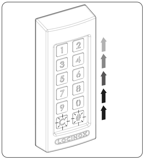
- If the sequence light stops, the relay is no longer energised. The SlimStone-2 is ready for a new code.
7.2 ENTER A WRONG CODE
- Enter a wrong code
- Press [#]to confirm the code
- All lights flash for 2 seconds, indicating a wrong code has been entered
- If 5 or more wrong codes are entered consecutively, you won’t be able to use the SlimStone-2 for a certain period due to safety reasons. The time out period is specified as follows : 2[number of failed attempts] seconds.
For example : 6 failed attempts result in a time out period of 64 seconds (26 seconds)
![]() The time out period is reset when a correct code is entered, or if no new code was entered during 2 hours.
The time out period is reset when a correct code is entered, or if no new code was entered during 2 hours.
MAINTENANCE
- Clean the housing and display using a soft cloth, moistened with a neutral cleaning agent
- Never use fuel or chemicals on the device since they might harm the housing
GENERAL INFORMATION
- Please observe the local regulations on the deposit of packaging material and of appliances no longer in use
- Our packaging material is eco-friendly. It can be divided into 2 materials: cardboard (box) and expandable polyester (buffer).
- Your device is made of recyclable materials
WARRANTY
A 2 year warranty covers all electronics
TROUBLESHOOTING

FREQUENTLY ASKED QUESTIONS

 A discarded device can either be returned to your dealer or be sent back to Locinox. This product’s recycling fee is € 0,2.
![]() The WEE marking on the product indicates that it may not be thrown away together with normal household waste and must be handed over to a designated collection point for the recycling of electrical and electronic rejects.
The WEE marking on the product indicates that it may not be thrown away together with normal household waste and must be handed over to a designated collection point for the recycling of electrical and electronic rejects.
![]() As manufacturer of this product, we guarantee that we have taken all the necessary steps in order to comply with the current safety requirements for this product.
As manufacturer of this product, we guarantee that we have taken all the necessary steps in order to comply with the current safety requirements for this product.


CONNECTION SCHEME

Doc. Nr.: MANU-000401
L o c i n o x nv • M a n n e b e e ks t ra a t 21
B-8790 Waregem • Belgium – Europe
Te l . + 32 ( 0 ) 56 7 7 27 6 6
E-mail: locinox@locinox.com
Locinox USA LLC • 460-464 Windy Point Drive
Glendale Heights • IL60139
Tel. 877-LOCINOX • Fax. 708-579-0978
E-mail: salesusa@locinox.com
![]()
