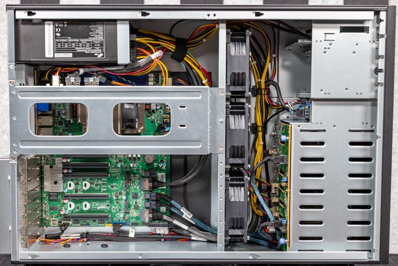
TYAN FT65T-B8030 AMD EPYC GPU Pedestal Server
Installation Manual

1 General Information
Read Me First
- The Barebone User’s Manual is available for download from our Web site at http://www.tyan.com. Make sure to read all precautions and instructions before you start installing the server system.
- Refer all servicing to qualified personnel to avoid the risk of damage to the server system.
- Exercise normal ESD (Electrostatic Discharge) procedures during system integration. TYAN/MiTAC recommends wearing gloves and an anti-static wrist strap to avoid possible damage to the equipment.
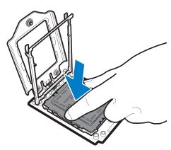
- Current processor socket design places the pins on the motherboard instead of the processor itself. Exercise caution when installing the processors as the manufacturer’s warranty does not cover damage inflicted upon the motherboard, including damage to the CPU sockets.
Box Content
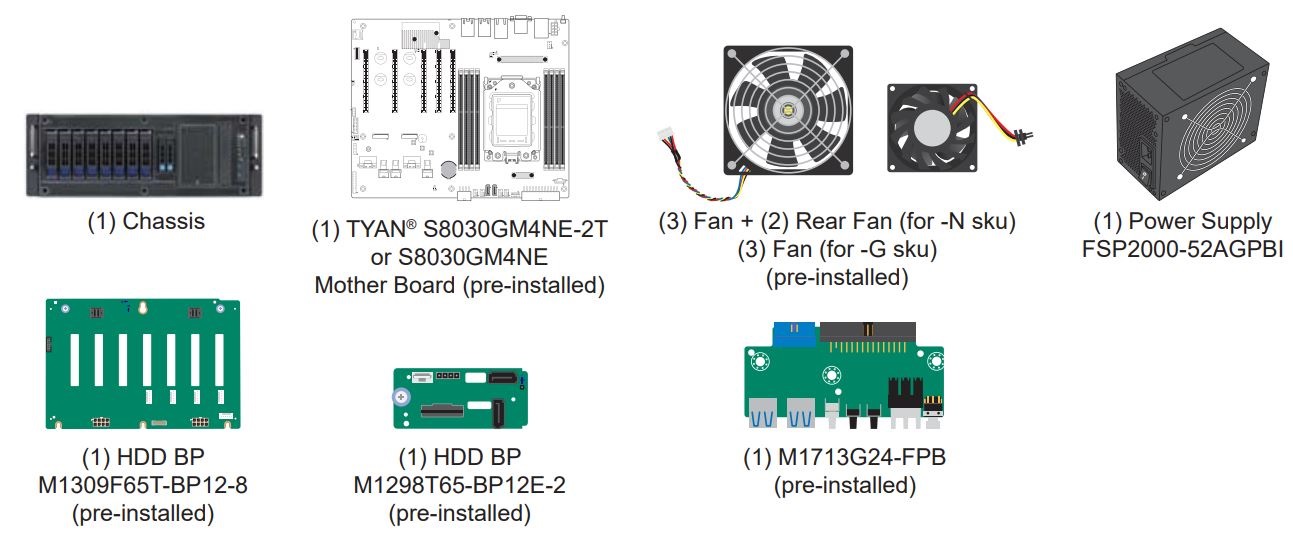
Accessories

Required Hardware Components
Minimum Hardware Requirements
To avoid integration difficulties and possible board damage, your system must meet the following minimum requirements:
- Processor: AMD EPYC 7002/7003 series processor w/ TDP up to 240W
- Memory Type: (8) DDR4 DIMM slots (8x memory channels) Support 2TB RDIMM/ LRDIMM DDR4 3200 memory
- Hard Disk Drives: (8) hot swap 3.5”/2.5” SAS 12Gb/s and SATA 6G (2) 2.5’’ SATA 6Gb/s and NVME
- Rack Mount Kit: Standard 19″ equipment rack
NOTE: The updated hardware requirements of the system please refer to the barebones user’s manual on our website at
http://www.tyan.com
Tools Required

2 System Installation
Open the Chassis

Preparing the Chassis
Read normal ESD (Electrostatic Discharge) procedures. Place your TYAN® Server Chassis on a flat anti-static surface to perform the following integration procedures. Read ESD procedures before reaching inside to install components.

Install the Front Hard Disk Drives (2.5”)
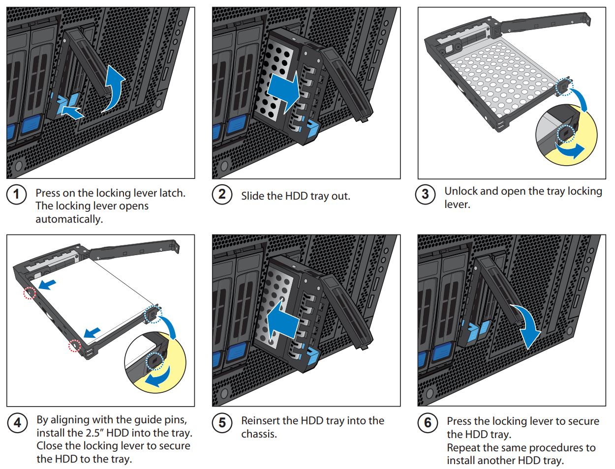
Install the Front Hard Disk Drives (3.5” or 2.5”)

Install the Processor
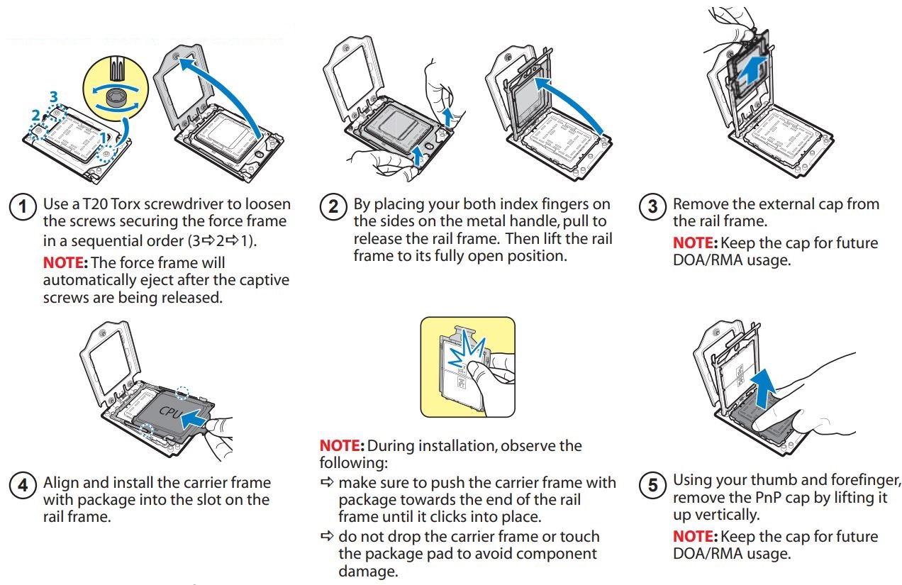
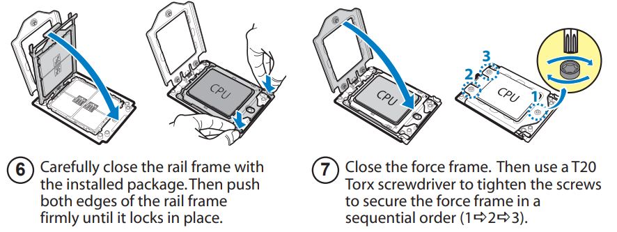
Install the CPU Heatsink

Install the Memory

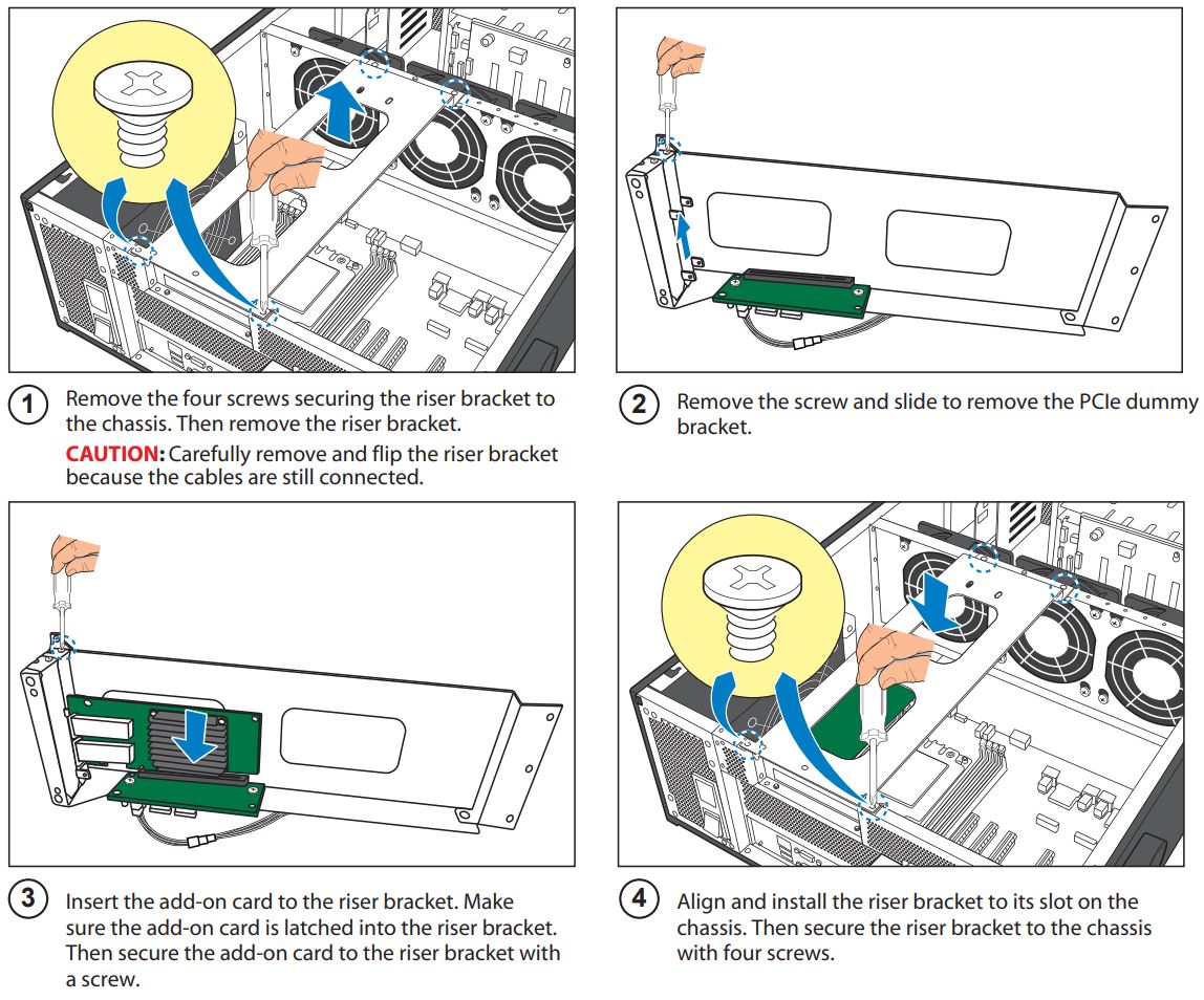
Installing the Add-On card (Optional)

3 Motherboard Placement
Motherboard Placement
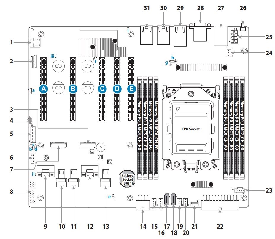
CONNECTORS
- Micro SD Connector (J19)
- System Fan Connector (J42)
- NVMe/SATA M.2 Slot (CN3)
- IPMB Header (J67)
- Front USB3.1 Header (J32)
- TPM Header (J40)
- NVMe/SATA M.2 Slot (CN1)
- Front Panel Header (J38)
- SlimSAS 8x Connector (CN4)
- MiniSAS HD Connector (J25)
- MiniSAS HD Connector (J26)
- SlimSAS 8x Connector (CN2)
- MiniSAS HD Connector (J27)
- 2x4pin PWR Connector (J65)
- System Fan Connector (J31)
- System Fan Connector (J18)
- SATA Connector (J22)
- SATA Connector (J14)
- System Fan Connector (J21)
- System Fan Connector (J17)
- CPU HP SMBus Connector (J44)
- 2x12pin PWR Connector (J60)
- PSMI Connector (J61)
- CPU Fan Connector (J34)
- 2x4pin PWR Connector (J63)
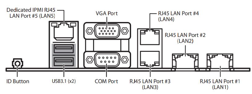
- ID Button
- Stacked USB3.1 x2 + IPMI LAN5 (J51)
- COM/VGA (J50)
- LAN3/LAN4 (J16)
- LAN2 (U93)
- LAN1 (U8)
LEDs
i ID LED
ii HDD Active LED
iii BMC LED
JUMPERS
- a BMC COM SELECT (J55)
- b RESET SELECT (J41)
- c BMC BYPASS SELECT (J43)
- d FPGA JTAG SELECT (J39)
- e CMOS CLEAR (J36)
- f ID BUTTON SWITCH (J101)
- g BMC COM SELECT (J56)
- h COM PORT SELECT (J15)
SLOTS
- A PCI-E Slot (J12)
- B PCI-E Slot (J9)
- C PCI-E Slot (J11)
- D PCI-E Slot (J10)
- E PCI-E Slot (J13)
4 I/O Ports
Locate the External I/O Port
5 Caution
DOA/ RMA Reminder
NOTE: Please save and replace the PnP Cap when returning the server board for service.
