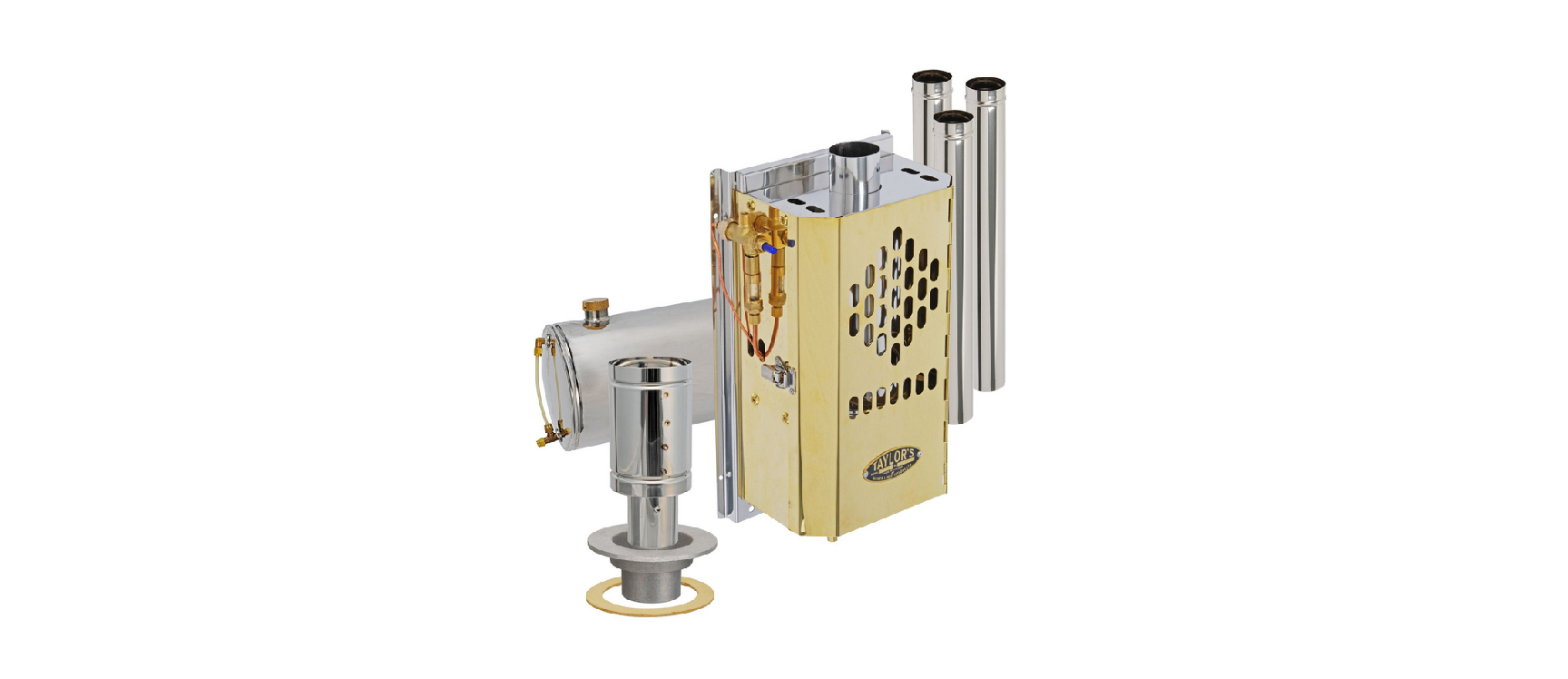
TOPLICHT 079D Taylor’s Diesel Cabin Heater Owner’s Manual
www.blakes-lavac-taylors.co.uk
INTRODUCTION
Congratulations on your purchase of a Taylor’s Cabin Heater.
Taylor’s Cabin Heaters are firm favourites with sailors throughout the world, providing their owners with a long and trouble free working life.
The Taylor’s Diesel Cabin Heater is simple to operate. After preheating, fuel is fed into the heater. The rate at which the fuel is fed into the burner pot determines the heat output. Within this handbook, you will find information and practical help on installing, running and maintaining your Cabin Heater.
If you require any further help or advice, please contact us either by email: bltsales@blakes- lavac-taylors.co.uk or by writing to: Seasure Ltd, Clock Tower Works, Shore Road, Warsash, SO31 9GQ
NOTE: please remember Diesel is a light heavy oil and will burn slightly more yellow than blue.
PRODUCT IMPROVEMENTS (MAR 1994).
All the following product improvements are available in current specifications – but older models can easily be upgraded.
The 079D can be run from the main diesel tank on the Boat – see section 6.4 for details (when ordering new heaters just ask for a pumped version of the 079D in brass (079DBP) or stainless steel finish (079DSP)).
- The drip feed has been upgraded. It now features a much “finer” drip feed control (36), adjustable to suit each individual installation (spares code for easily retro- fitted update kit is *HTD5254).
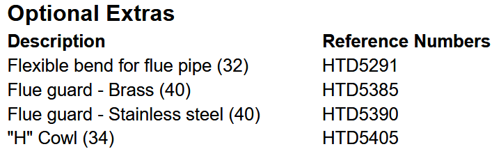
- Taylors have now made available an attractive flue guard in stainless steel or brass (40)
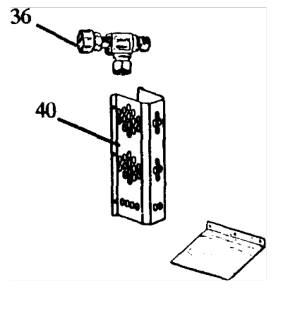
Heat Reflector Plate can be fitted.
INSTALLATION KIT PROVIDED WITH YOUR HEATER
Taylors Diesel Cabin Heaters are provided with the following parts for installation and subsequent operation:
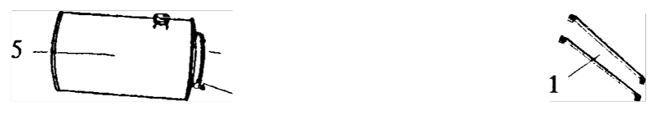
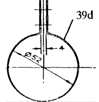
- 1 1/2 Gallon Gravity tank and securing straps
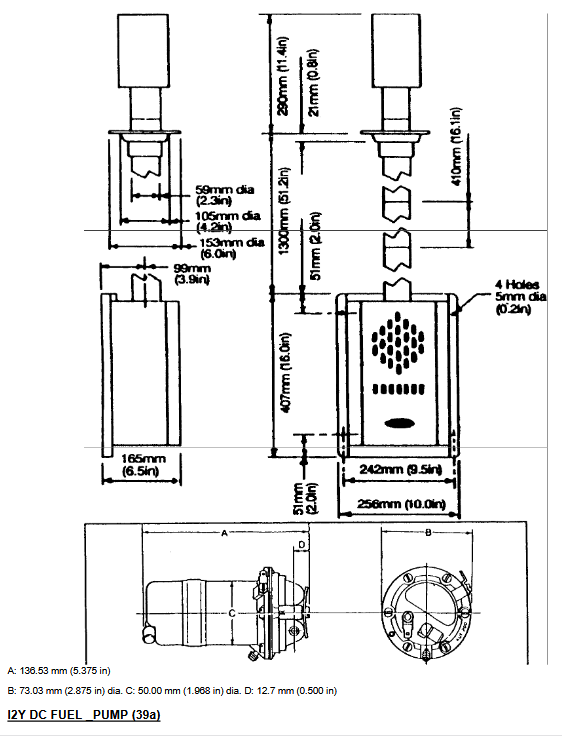
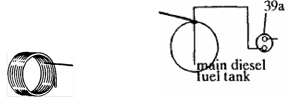
ALTERNATIVELY, for Main Fuel tank Pumped Systems - 12V DC SU pump (39a) (24V DC conversion resistor (39b) always included), with main fuel tank standpipe 41 assembly (39c) and extra 5m of Copper fuel pipe (41).
- 3 lengths of Stainless Steel flue pipe each of 18″ (457mm) in length and 56mm width. Note: Ideally, 3 lengths should be fitted for clean burning i.e. 51″ (1295mm) after interlocking. In practice, the length can be reduced to an absolute minimum of 30″ (it is possible to put further lengths above deck, which if done, must be insulated).
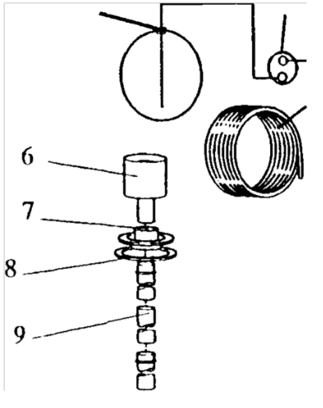
- Through Deck-fitting, gasket and cowl (6,7,8,9)
- 3 metres of Copper fuel pipe and compression fittings (10)
- Safety On-off fuel control valve (12)
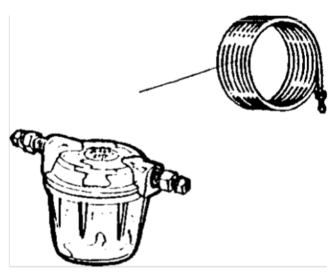
- In-line fuel filter (11)
- Methylated Spirits dispenser (13)
Because the nature of an installation varies from owner to owner, certain components are easier to source locally. We therefore feel it is best for you to purchase the following separately, depending on your requirements.
- Mill board with Stainless Steel cladding or ceramic tiles if extra insulation between heater and bulkhead is required.
- 4 x 6mm (1/4″) diameter Stainless Steel securing bolts or screws for deck fitting (length may vary according to deck thickness and possible cambering).
- 4 x 6mm (1/4″) diameter Stainless Steel securing bolts or screws for fixing tank straps.
EXPLODED DIAGRAM
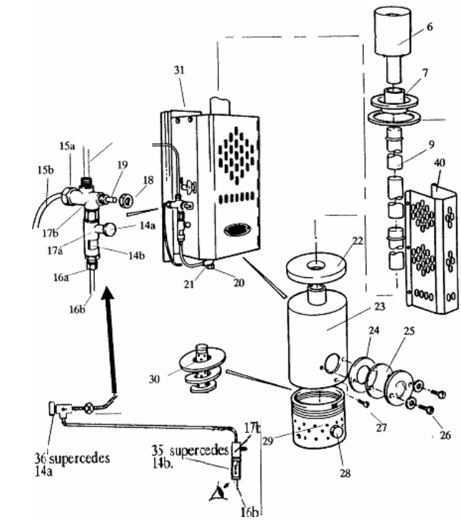
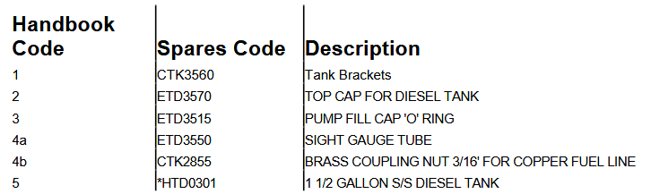
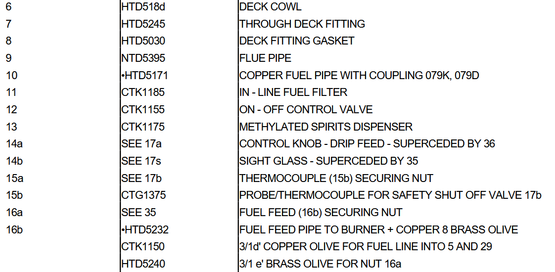
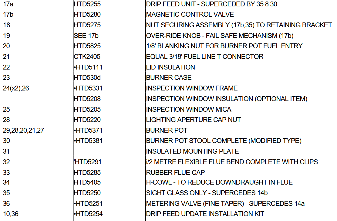
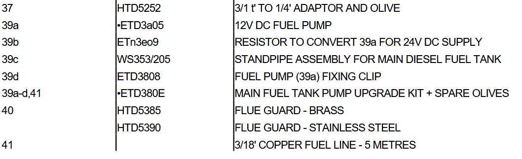
SPARE PART REFERENCE NUMBERS
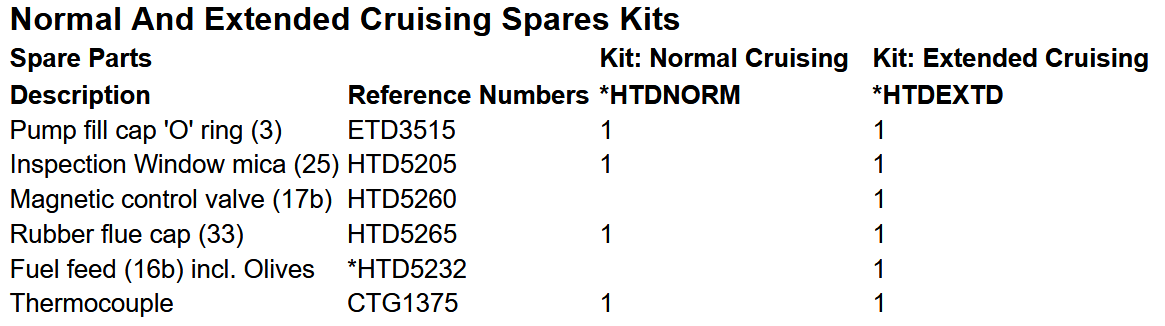
ON-BOARD SPARES KITS AND ACCESSORIES
A complete range of spare parts and on-board spares kits for the Taylor’s Diesel Cabin Heaters are available. Reference numbers for the item numbers on the exploded diagram are detailed in Section 4.
Blakes-Lavac-Taylors, the manufacturers of Taylor’s Cabin Heaters, supply spare parts and kits only through the marine trade (chandlers and boat builders). Overseas, spare parts and kits are supplied through appointed agents. If you require spare parts, on-board spares kits or help in locating a local chandler or agent, wherever you are in the world, please contact us or refer to our website. www.blakes-lavac-taylors.co.uk Our address and telephone number can be found on the back of this leaflet.
The on-board spares kits for Taylor’s Diesel Cabin Heaters provide the ideal combination of spare parts to help you maintain your Cabin Heater whether ashore or cruising at sea.
INSTALLING YOUR HEATER
CHOOSING THE POSITION
The heater has been designed to be mounted on a vertical bulkhead and it is recommended that it be situated with the base at an approximate height of NOT LESS THAN 225mm (9″) from the floor. Although the heater mounting plate (31) is insulated, it is suggested that the heater is set on a reflective or insulated surface. The surface should have a margin of at least 150mm (6″) around all four sides of the heater mounting plate. Suitable materials would be 1/8″ mill board insulation with a stainless steel cladding or ceramic tiles.
- DO NOT mount the heater over a combustible surface because spillage would be damaging and could present a fire hazard.
CONSTRUCTING THE FLUE
Ideally, 3 flue lengths (9) should be fitted for clean burning i.e. 51″ (1295mm) after interlocking flue sections each of 457mm (18″). In practice, the length can be reduced to an absolute minimum of 30″. If this length cannot be fitted inside the cabin, it will be necessary to fit additional flue sections outside the cabin when the heater is in use. To maintain an adequate draught for clean combustion, any flue lengths outside the cabin should be insulated. A simple method of insulation is to bind the flue with thin heat resistant cord.
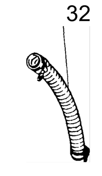
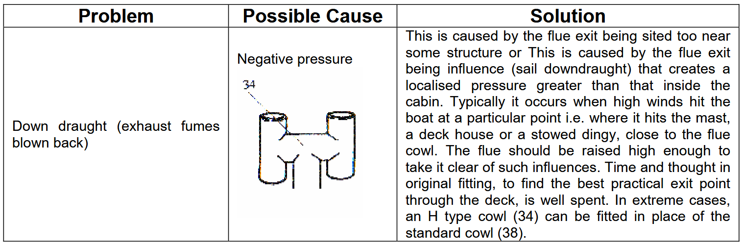
It is highly desirable for the flue to be vertical and straight to ensure a sufficient draught for clean and efficient combustion. The flue outlet must be clear of obstructions and located in an area that has an undisturbed air flow and no down draughts from sails, masts, deck structures etc. If absolutely necessary, the flue can be fitted with a flexible section (32). The maximum angle of bend in the flexible section is 45 ° .
A 108mm (4 1/2 “) diameter hole is required through the deck to receive the deck fitting. The fitting is supplied undrilled and suggested fastenings (not supplied) are 4 x 6mm (1/4”) diameter stainless steel bolts.
An insulating gasket (8) is provided for insulation between the deck fitting and the deck. Deck camber can be accommodated by fitting timber pads or by using a low density peroxide resin filler to give a flat area on which to position the deck fitting.
To ensure a watertight joint, a bead of silicone sealer should be put around the outer edge of the deck fitting (7) and also around the fastenings.
SITING THE FUEL TANK (gravity feed systems)
The basic 079d – heater installation utilises a gravity fed fuel supply. The 1 gallon Stainless Steel fuel tank (5) and :V16″ copper fuel pipe (10) should be sited above the heater so that a head of fuel of at least 1220mm (4′) is present above the heater drip feed assembly. Note: if space is tight, installations where only 600mm (2) is available are still feasible. If this is still not possible then siting the tank in a locker on deck should be considered or alternatively, pressure can be introduced with a special tank cap (2) with integral car tyre valve (available on request from the factory). Essentially, a slight pressure of 0.4 psi per foot of lost head is required. This is easily introduced by a few strokes on a bicycle pump. The tank is supplied with 2 straps (1) for mounting the tank on a bulkhead or locker floor.
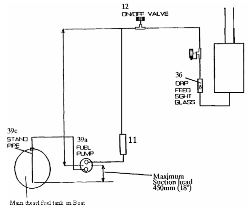
PUMPING FROM THE MAIN DIESEL TANK
TAYLOR’S NEW 079D “POWER PUMP” DIESEL HEATER – FEATURES
An electric pump version of the extremely successful gravity fed Taylor’s 079D diesel heater is available. This system will work with a 12V DC or 24V DC supply and is available also as a retrofit kit (spares code *ETD3606).
The 079D heater has always been popular because of the safety feature offered by its unique drip feed system. When there is any danger of heeling a “drip feed system” is far less susceptible to heeling than car burettor systems where the “float level control” can flood the heater if the boat heels badly. The option to pump straight from the main diesel tank on the boat using only a minute current draw – 0.01 Amp/hr to be precise – is obviously very attractive. This alternative installation has been tested for many years now by customers to pump fuel directly from the boat’s main fuel tank to either one or two 079D heaters.
The 12V DC diaphragm pump provided is not only very robust but it as shown in the example below, with two heaters; it uses a minute amount of electricity:
Example. The capacity of the pump is 32 litres an hour. Pumping to two 079D heaters requires (at maximum heat) about 0.4 litres an hour. This equates to running the pump at just over 1% of capacity. The pump operates against a spring so it provides a constant pressure but only uses current when it pulses. In practice a flow of 0.4 litres, an hour is around three pulses a minute. With an induction coil current of 3.5 Amps over a pulse period of 85 milliseconds, this rates it at only 0.01 Amp/hr!
Key points:
- Works with a 12V DC or 24V DC supply – see section 6.4.4.
- Power consumption is very small, (0.01 amp hours), since the pump is only operating at a few pulses per minute.
- The heaters can be sited up to 22 metres from the tank (with the pump only working at 1% capacity, greater distances are no doubt possible).
- The pump will cope with up to 1.8m delivery head (adequate for just about any installation).
- All pipe work is metal; there are no flexible, rubber or plastic hoses.
- No separate gravity feed day tank required.
- Smooth drip feed rate even at long delivery distances.
INSTALLATION KIT ITEMS
- 12V DC S.U. pump assembly (39a) with conversion resistor (39b) for 24V DC supply and fixing clip (39d).
- Stand pipe assembly (39c)
- 5-metre length of 3/16″ Copper fuel pipe (41- Note: this item is extra to copper fuel line complete with coupling (10) – see section 6.5).
INSTALLATION FOR PUMPED FUEL SUPPLY FROM MAIN DIESEL TANK
INSTALLATION – FITTING OF STANDPIPE
Do not attempt to Tee into the fuel pipe going to the engine as this may allow air to be drawn back into the engine fuel line. If an auxiliary fuel tap or gallery is not available on the main fuel tank, you will need to access the fuel tank with a standpipe (39c).
A Standpipe (39c) is provided with the installation kit. Ascertain the best position for the standpipe avoiding any obstructions within the tank (such as a level gauge). If necessary cut to ensure the end of the pipe is no closer than 25mm from the bottom of the tank.
Use a 25rum tank cutter to make a hole in the tank taking care to use grease on the cutter and drill to collect any swarf.
INSTALLATION – FUEL PUMP
The fuel Pump should be located close to the main diesel fuel tank. The key constraints are the suction head and delivery head. The maximum recommended suction head is 450mm (18″) and the maximum recommended delivery head is 1770mm (70″). If the depth of the main diesel fuel tank is greater than the suction head then simply locate the fuel pump (39a) lower down by looping the copper fuel pipe down to the fuel pump (diagram on previous page exemplifies this). Installations have been satisfactorily tested where a 900mm (36″) standpipe (39c) has been looped down to the fuel pump to give an effective suction height of 450mm (18″) i.e. the fuel siphons up and down to the fuel pump.
The fuel pump (39a) should be fixed in place (a bracket (39d) is provided) ensuring the outlet port is located above the inlet port – protection from vibration should be a consideration – see section 6.4.5. Note that flexibility is possible re direction of inlet and outlet ports by undoing clamp and rotating ports.
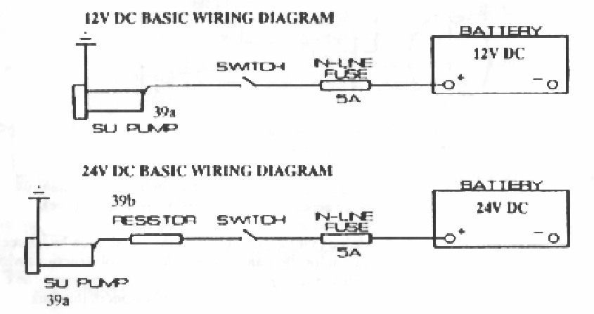
WIRING DIAGRAMS
If you are wiring up the 12V DC pump to a 24V DC system then wire up the resistor (39b) provided as in the wiring diagram below.
INSTALLING THE FUEL LINE
Please refer to sections 6.5 and 6.6. An extra 5 metres of copper fuel is provided. If your installation requires more fuel, line or fuel fittings then please write in. In addition to the points in sections 6.5 and 6.6, we suggest you put a loop in the fuel line between the main diesel fuel tank and the fuel pump to help insulate the fuel pump (39a) from vibration in and around the engine compartment.
ASSEMBLING THE FUEL SUPPLY PIPE
The 3/16″ copper fuel pipe (10) is supplied with compression fittings. All other compression fittings and olives are in the various components – depending on gravity pumped fuel supply: on-off valve (12), in-line fuel filter (11), and pump (39a), and standpipe (39c), bottom fitting of gravity tank (4b). With heater installations that pump fuel direct from the main diesel tank an extra 5 metres of 3 / 1 6 ” copper fuel pipe (41) is supplied.
LOCATIONS OF FUEL LINE COMPONENTS
The in-line fuel filter (11) should be inserted in the copper fuel pipe in a readily accessible place as close to the gravity tank or main diesel tank as possible. This means that if any debris does enter the fuel line from the tank it will be easier to isolate and blow out the fuel line.
The drip feed valve (36) and on-off valve (12) should be located as shown in the diagram below:
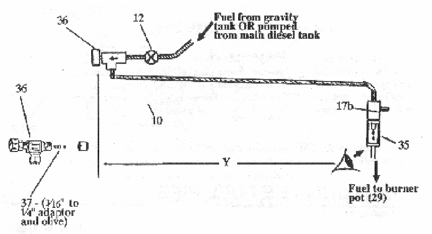
KEY POINTS REF DIAGRAM ABOVE:
- Distance Y between Eye and metering valve (36) should be within easy arms reach.
- Locate the on-off control valve (12) as close to the heater as possible to minimise delay between turning off the valve (12) and stopping fuel supply to the heater.
Having decided on sensible locations for the fuel line components tile fuel line can be cut to suit. All joints use compression fittings.
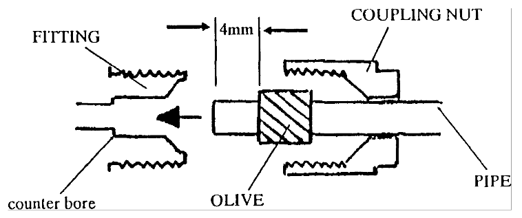
ASSEMBLING THE COMPRESSION FITTINGS
When assembling the compression filling (see diagram below), ensure that the copper pipe is cut at right angles and that all swarf and burrs are removed. Slide on the coupling nut and then the olive so that the pipe protrudes about 4mm from the olive. Push the pipe into the fitting until the end of the pipe touches the counter bore in the fitting. Tighten the coupling nut gently and then undo to check that the olive has formed evenly around the pipe. Finally, reassemble and tighten the coupling nut just enough to prevent leakage. Over-tightening the coupling nut will deform the olive and the compression fitting will not seal.
FIXING THE FUEL PIPE
Care must be taken to prevent the fuel pipe (10 & 41) vibrating as vibration will cause the pipe to fatigue and eventually fracture. The pipe should be clipped into position at frequent intervals and protected from mechanical damage. One way to protect against damage and vibration is to run the fuel pipe in clear PVC hose and fasten with bulkhead clips or cable lies to the hull structure.
COMMISSIONING YOUR HEATER
PRELIMINARIES
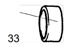
Remove the flue cap (33) and fit the cowl (38). Close the metering valve (36) and on-off valve (12).
PRIMING THE SYSTEM
Note: no fuel will pass the magnetic safety valve (17b) until the burner pot (29) is pre-heated and the blue knob (19) fully depressed see next section 73.
GRAVITY TANK SYSTEMS
Quarter fill the fuel tank (5) with clean diesel. Open both valves 36 and 12 and check for leaks around the tank and in the pipe work up to the magnetic valve (17b). Leakage from the compression fittings can normally be stopped by tightening the nut on the fitting. Leaks that persist after the fitting has been tightened will require re-making the fitting with a new olive.
The tank can be filled from the main diesel tank using a pump such as the Henderson Chimp. Alternatively, the tank can be filled from the deck via a suitable hose and deck fitting.
Complete the filling of the gravity tank (5) – DO NOT FILL TO THE TOP – and fit the filler cap (2) ensuring the air vent arrangement is open (allowing equalisation of pressure as the fuel level drops in the tank). Do this by tightening down the cap (2) and then undoing 2 a few turns.
MAIN FUEL TANK PUMPED SYSTEMS
Ensure fuel pump is correctly installed see section 6.4. Turn on valves 12 and 36. Loosen coupling nut of compression fitting between fuel line 10 and 17b. The Fuel pump 39a should pulse (tick) at a fast rate until all air is expelled, then re-tighten coupling nut.
PRE-HEATING THE BURNER POT
Remove the cap nut (28) to give access to the burner pot (29) for priming with methylated spirit. Use the dispenser (13) provided to cover the base of the burner pot (29) with methylated spirit (approximately 20cc).
Light the burner through the same aperture with a taper or match. Once the methylated spirits has been burning for about half a minute, replace the cap nut and allow the burner pot to heat. The cap nut (28) should not be removed during normal operation of the heater. The centre stool (30) can be seen through the burner case inspection window (25). After 3- 4 minutes, the centre stool will gradually heat up. There should be a fan of blue flames visible through the 19-inspection window.
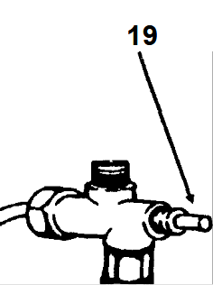
As the blue flames start to diminish, indicating that the pre-heating methylated spirits has nearly finished burning, press the blue knob (19) fully home for aboutl5seconds and then release it. – This over-rides the fail safe in the magnetic control valve (17b).
Fuel will now be seen dripping through the sight glass (35). Adjust the fuel feed rate by rotating the knob on metering valve (36) so that the drip rate is about 110 drips per minute. This rate will vary slightly between installations. The drip rate should be set so that the heater is burning as much fuel as possible with minimum smoke being emitted from the flue – see section 7.4.
MAXIMUM DRIP RATE SETTING
The “Maximum” drip rate must be set for each installation when commissioning or subsequently re-setting the heater. The maximum drip setting is about 120 drips a minute as beyond this fuel oversupply causes inefficient combustion and environmentally “unfriendly” smoke to be emitted from the flue.
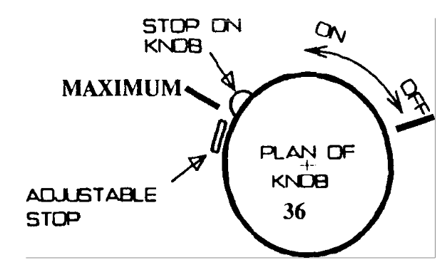
The fine taper metering valve (36) offers much finer control at a point remote from immediate heat conduction. The difference between “Off” and “Maximum” is less than 360 ° allowing the incorporation of an adjustable stop. The adjustable stop works by limiting the opening of the metering valve by engaging the stop on the knob – see diagram on previous page. The adjustable stop is locked in position by tightening the lock nut.
The typical drip rate range for a heater with 3 lengths of flue (as supplied), after the initial pre-heating stage described above, is between 80-110 drips per minute. It can work outside this range but the optimum setting gives a blue/yellow flame. This is the cleanest burning pattern and minimises the degree of sooting up. Always:
- Adjust the drip rate down to the desired heat setting.
- Note that drip-setting changes should be made gradually and the heater allowed to stabilise between setting changes.
EXTINGUISHING THE BURNER
To extinguish the heater simply turn off the on-off valve (12). The flame in the burner pot (29) will gradually die down as the remaining fuel is burnt off. There should be no need to touch the setting of the metering valve (36). The advantage with this procedure is that subsequent re-starts are very straightforward – see section 7.6…
SUBSEQUENT RE-LIGHTING
Having previously extinguished the burner as per section 7.5, the procedure is simple:
- turn on on-off valve
- pre-heat burner pot as explained in section 73
Drip rate and hence heat output will be at previous setting.
WARNING
SHOULD THE FLAME IN THE BURNER POT (29) BE EXTINGUISHED FOR ANY REASON DO NOT ATTEMPT TO RELIGHT THE BURNER UNTIL IT HAS COOLED DOWN TO ROOM TEMPERATURE AGAIN
If the flame has extinguished unexpectedly i.e. circumstances other than those outlined in section 7.5, then always check the burner pot (29) is empty of fuel prior to re-lighting. Undo nut (20) to drain.
SAFETY PROCEDURES
IMPORTANT
Simple cabin heaters of the” open flame” type, like this Taylors model, have been in safe use for many years. Their very simplicity, however, dictates that they must not be confused with the more sophisticated and expensive automated heating systems now available.
- THEY SHOULD NEVER BE LEFT TO RUN COMPLETELY UNATTENDED.
- SHOULD THE FLAME IN THE BURNER POT (29) BE EXTINGUISHED FOR ANY REASON DO NOT ATTEMPT TO RELIGHT THE BURNER UNTIL IT HAS COOLED DOWN TO ROOM TEMPERATURE.
- IF THE FLAME HAS EXTINGUISHED UNEXPECTEDLY, IE. CIRCUMSTANCES OTHER THAN THOSE OUTLINED IN SECTION 7.5, THEN ALWAYS CHECK THE BURNER POT (29) IS EMPTY OF FUEL PRIOR TO RE-LIGHTING. UNDO NUT (20) TO DRAIN.
EMERGENCY FIRE PROCEDURE
Close the safety control on-off valve (12)
Control the flames by smothering them with a fire blanket or by the use of an approved fire extinguisher, which should be installed and readily available as part of the boat’s standard safety equipment.
- NOTE: DO NOT ATTEMPT TO CONTROL THE FIRE BY THROWING WATER OVER THE APPLIANCE.
CHECKPOINTS
MAINTAINING YOUR HEATER
CLEANING THE FUEL ENTRY POINT
Remove nut (20) to allow access to clean the fuel entry point using a pipe cleaner or similar utensil.
COMPLETE OVERHAUL
Open the door. Where the fuel pipe (16b) connects into the T-connection (21) undo the nut and free the fuel pipe.
Pull the thermocouple (lSb) out of the burner pot (29).
Remove the screw (27) that secures the burner pot into the burner case (23) and withdraw the burner pot (29).
Remove the burner stool (30) from the burner pot and clean out all soot. Clean out the burner pot and ensure that the fuel entry point is cleaned as described in section 10.1.
Re-assemble in reverse order. Be careful not to over-tighten the nut connecting the fuel pipe (16b) to the T-connection (21). Check that it is leak proof when the heater is next used.
Note: if you damage the fuel pipe (16b) then you will need to replace it complete with compression fittings (*HTD5232). This is available as a standard item in the Extended Cruising Spares Kit – details in Section 5.
If burner stool is tight and can not be removed, immerse burner pot and stool in a small container of paraffin for 24 hours. Then wiggle from side to side and pull stool out.
DIMENSIONS AND SPECIFICATIONS
Pre-Heating Fuel – Methylated Spirits (alcohol)
Fuel – Diesel or Paraffin (kerosene).
Fuel Consumption – 0.2 litres at full heat per hour.
Heat Output – Reflected at 600mm (2) distance: 2.4kWh.
Installation Kit –
- 1’/2 gallon gravity tank.
- 3 lengths of Stainless Steel flue pipe. ~ Through-deck fitting and cowl.
- 3m of copper fuel pipe. ~ In-line fuel filter.
- Safety on-off control valve. ~ Pre-heating fuel dispenser.
- Fine control valve.
Weight — Approx 11kg.
GRAVITY OR PUMPED FROM MAIN FUEL TANK – SEE SECTION 6.4 FOR DETAILS ON PUMPED VERSION
DIESEL TANK DIMENSIONS
Length 340mm (13.4”)
Height 230mm (9.1″)
Width 178mm (7″)