talkpool OY1211 LoRaWAN CO2 Meter Manual
1 Disclaimer
This document represents information on products at the time of publication and is subject to change without prior notice due to product improvements or other reasons. Talkpool makes no warranties based on the accuracy or completeness of the contents of this document and reserves the right to make changes to specifications and product descriptions at any time without notice. Talkpool reserves all rights to this document and the information contained herein.
1.1 Technical support
Please visit www.talkpool.com for additional information, or contact IoT.support@talkpool.com
1.2 FCC compliance statement
FCC ID: 2A6VH-OY1211 IC: 28553-OY1211
This device complies with part 15 of the FCC Rules. Operation is subject to the following two conditions: (1) this device may not cause harmful interference, and (2) this device must accept any interference received, including interference that may cause undesired operation. CAUTION: The grantee is not responsible for any changes or modifications not expressly approved by the party responsible for compliance. Such modifications could void the user’s authority to operate the equipment.
NOTE: This equipment has been tested and found to comply with the limits for a Class B digital device, pursuant to part 15 of the FCC Rules. These limits are designed to provide reasonable protection against harmful interference in a residential installation. This equipment generates, uses, and can radiate radio frequency energy, and if not installed and used in accordance with the instructions, may cause harmful interference to radio communications. However, there is no guarantee that interference will not occur in a particular installation. If this equipment does cause harmful interference to radio or television reception, which can be determined by turning the equipment off and on, the user is encouraged to try to correct the interference by one or more of the following measures:
- Reorient or relocate the receiving antenna.
- Increase the separation between the equipment and receiver.
-Connect the equipment into an outlet on a circuit different from that to which the receiver is connected.
– Consult the dealer or an experienced radio/TV technician for help.
1.3 RF exposure statement
This equipment complies with the FCC RF radiation exposure limits set forth for an uncontrolled environment. This equipment should be installed and operated with a minimum distance of 20cm between the radiator and any part of your body. Canadian Compliance Statement This device contains license-exempt transmitter(s)/receiver(s) that comply with Innovation, Science and Economic Development Canada license-exempt RSS(s). Operation is subject to the following two conditions:
(1) This device may not cause interference.
(2) This device must accept any interference, including interference that may cause undesired operation of the device.
1.4 RF exposure statement
This equipment meets the exemption from the routine evaluation limits in section 2.5 of RSS102. It should be installed and operated with a minimum distance of 20cm between the radiator and any part of your body.
2 Warnings
The following safety precautions must be observed during all phases of the operation, usage, service or repair of this Talkpool product.
- Read the product manual.
- Do not modify the product.
- The product should not be exposed to extreme heat or open flame.
- The device must not be exposed to harsh chemical agents or solvents.
- The labelling of the product may not be changed, removed or made unrecognizable.
3 Environmental
![]() This symbol on the product or on its packaging indicates that this product must not be disposed of with your other household waste. Instead, it is your responsibility to dispose of your waste by taking it to a collection point designated for the recycling of electrical and electronic appliances. Separate collection and recycling of your waste at the time of disposal will contribute to conserving natural resources and guarantee recycling that respects the environment and human health. For further information concerning your nearest recycling center, please contact your nearest local authority/town hall offices, your household waste collection company or the shop where you bought the product.
This symbol on the product or on its packaging indicates that this product must not be disposed of with your other household waste. Instead, it is your responsibility to dispose of your waste by taking it to a collection point designated for the recycling of electrical and electronic appliances. Separate collection and recycling of your waste at the time of disposal will contribute to conserving natural resources and guarantee recycling that respects the environment and human health. For further information concerning your nearest recycling center, please contact your nearest local authority/town hall offices, your household waste collection company or the shop where you bought the product.
4 Product Description
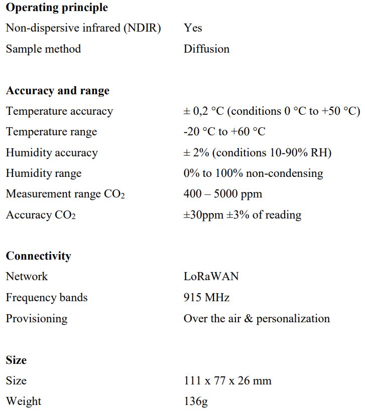
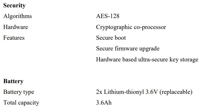
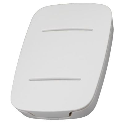 The OY1211 LoRaWAN CO2 meter is designed to measure carbon dioxide, temperature and humidity in indoor environments. The sensor is intended for indoor climate control, air quality monitoring and energy optimizations. It is optimized for reliable and secure measurements with more than 5-10 years life length on batteries dependent on radio conditions.
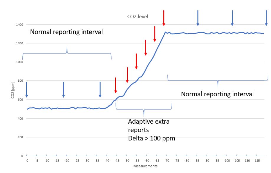
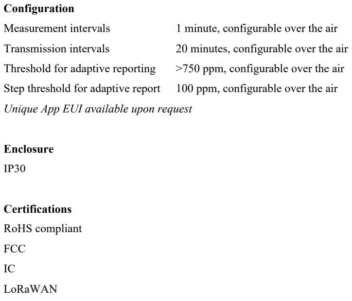
The standard measurement interval is every minute and standard reporting interval is every 25 measurements (resulting in a measurement report transmitted every 25 minutes). The fast measurement interval makes it possible to insert additional transmissions when large changes in the CO2 level are detected, resulting in low reporting latency. By default, CO2 level changes larger than +/-100ppm from the last transmitted measurement report causes an additional measurement report over the LoRa uplink channel. If the absolute CO2 level is below a certain threshold, by default 750ppm, these additional reporting events are however omitted. All these parameters can be adjusted using LoRa downlink commands if needed. (elaborate and make more available for non-tech) What value does this provide, climate control, active ventilation etc.
5 Advanced settings
The device has advanced settings that such as configuration of automatic background calibration (ABC) functionality, target calibration, and sub-sample settings. The settings are impacting the power and accuracy performance of the device. Contact iot.support@talkpool.com for detailed information.
OY1211 LoRaWAN CO2 meter, User manual, Version
6 Installation and activation
The sensor consists of a bottom piece, the electronic board and the top cover. Remove the top cover by pressing it upwards and outwards. The electronics are removed by releasing the plastic latch on the top.
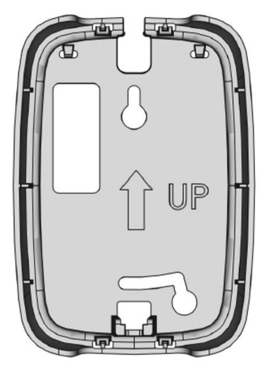
The bottom piece is mounted on the wall with the “UP” arrow upwards. It can be mounted either with screws or adhesive tape.
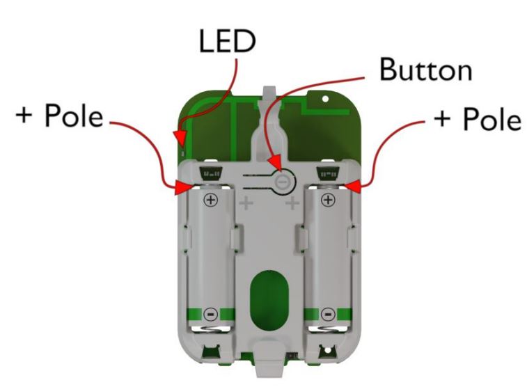
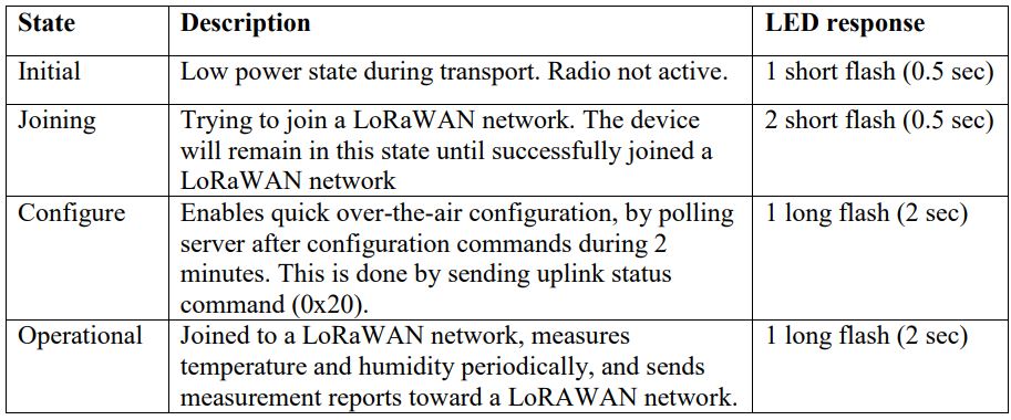
Configure the device in the LoRaWAN server, according to chapter 5.1, and insert the batteries. The sensor starts and flashes 2 + 6 times during the boot-up sequence. The sensor is activated by pressing the push button for 3 seconds until the red LED makes two short flashes. When the device has successfully joined the LoRaWAN network there will be a 2second-long flash. Attach the electronic board to the bottom piece and attach the plastic cover.
6.1 LoRaWAN Configuration
Configuration on the network server is done with AppEUI: 70-B3-D5-D7-2F-F8-18-00 (a.k.a. JoinEUI) It is possible to order a batch of devices configured with a customer unique AppEUI from the Talkpool OUI range.
The device is configured with device unique DevEUI and AppKey. The DevEUI is printed on device box and the AppKey is distributed by the sales team. The device is default configured for OTA provisioning. Contact the Talkpool team for ABP configuration. The device follows the LoRaWAN standard related Join configuration parameters, such as RX1 and RX2 windows, RX2 downlink frequency etc. The default setting is ADR enabled. If you are not experienced of LoRaWAN, contact iot.support@talkpool.com to get started.
6.2 Sensor states and state check
The sensor has five states: Booting, Initial, Joining, Configure and Operational state.
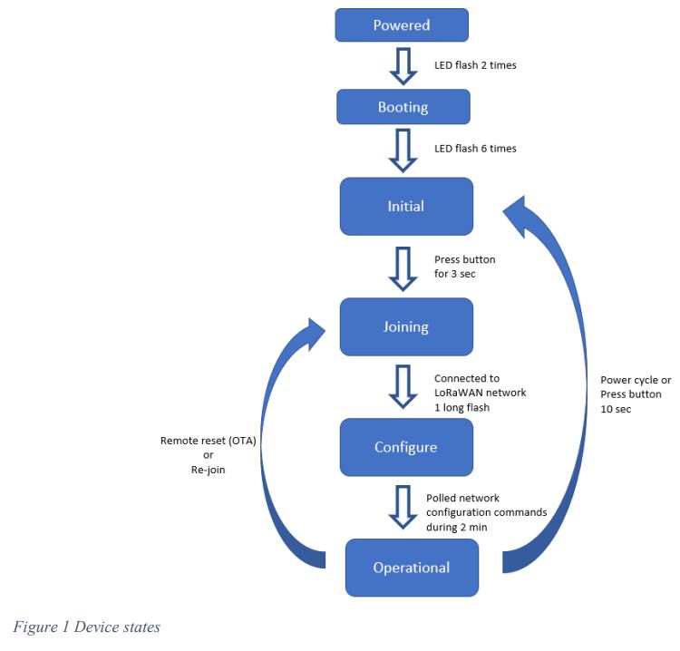
When the unit is initially powered, it flashes 2 times with the LED, after a few seconds the unit enters initial state automatically. This is indicated by flashing 6 times. To check the device state, press the button and hold it pressed until the red LED starts flashing after 0.5s.
6.2.1 Re-join functionality
The device supervises its connectivity to the network, by monitoring that periodic downlink messages are received. The device tries to re-join the network if it has not heard anything from the network for 288 uplinks (4 days @ 20-minute message interval). The device requests and normally gets a downlink ever 64th uplink due to the ADRAckReq functionality.
6.3 Measurement and reporting interval
The measurement interval and reporting interval can be set with downlink commands. The default setting is a measurement interval of 60 sec. The default reporting interval is every 25th measurement interval. The device sends extra reports when above a configurable CO2 level, default setting 750 ppm and larger difference than 100 ppm from last report. The reporting interval counting is reset after an extra measurement report
7 Specification
8 Battery life
Storage
More than one year without limiting the product life length
Operational
Battery life length
>5 years (at 25-minute intervals, SF12) + 1 year storage
9 Security
The device has the following security features:
- Cryptographical coprocessor for ultra-secure hardware based key storage
- Secure boot
- Encrypted FW
- Message encryption (AES-128 bit)
- Message integrity (MIC AES-128 bit)
- No port access to device.
10 Protocol
The protocol consists of different types of data
– LoRaWAN v.1.0.2 standard commands
– Unsolicited uplink status commands during configure state
– Periodic measurement reports
– Downlink commands and queries
– Uplink query response
Note 0x denotation means hexadecimal encoded.
10.1 LoRaWAN standard commands
All standard LoRaWAN v 1.0.2 Rev B are supported. Please refer to the LoRaWAN standard for the protocol definition.
10.2 Unsolicited uplink status commands
The sensor polls the server for configuration parameters the during the Configure state. This is done by sending unsolicited uplink status report (0x20). This gives quick feedback to the installer that the installation has been successful and enables downlink configuration commands to be sent. After approximately 2 minutes the device changes to Operational state. See chapter 6.5 for details of the Status report.
Port: Port 1
Payload 0x01 20 00
0x01: Data type
0x20: Status command
0x00: Normal start-up
The expected behaviour is 0x01 20 00. If not contact support. 10.3 Periodic measurement reports
The sensors transmit periodic unsolicited measurement reports or adaptive reports due to changes in CO2 level.
10.3.1 Periodic measurement report
The default configuration is that temperature, humidity and CO2 level are transmitted every 20th minute. The data is packed into minimal number of bytes to conserve energy and to minimize interference. Port: Port 2 Payload: Measurement value (see chap 9.3.2) Size: 5 Bytes
10.3.2 Measurement value
The measurement value for each measurement
Byte 0: Temperature, bit 11 – bit 4
Byte 1: Relative humidity, bit 11 – bit4
Byte 2:
bit 7-4: Temperature, bit 3 – bit 0
bit 3-0: Relative humidity, bit 3 – bit 0
Byte 3-4: CO2 sent as an unsigned 16-bit integer

10.3.2.1 Temperature conversion
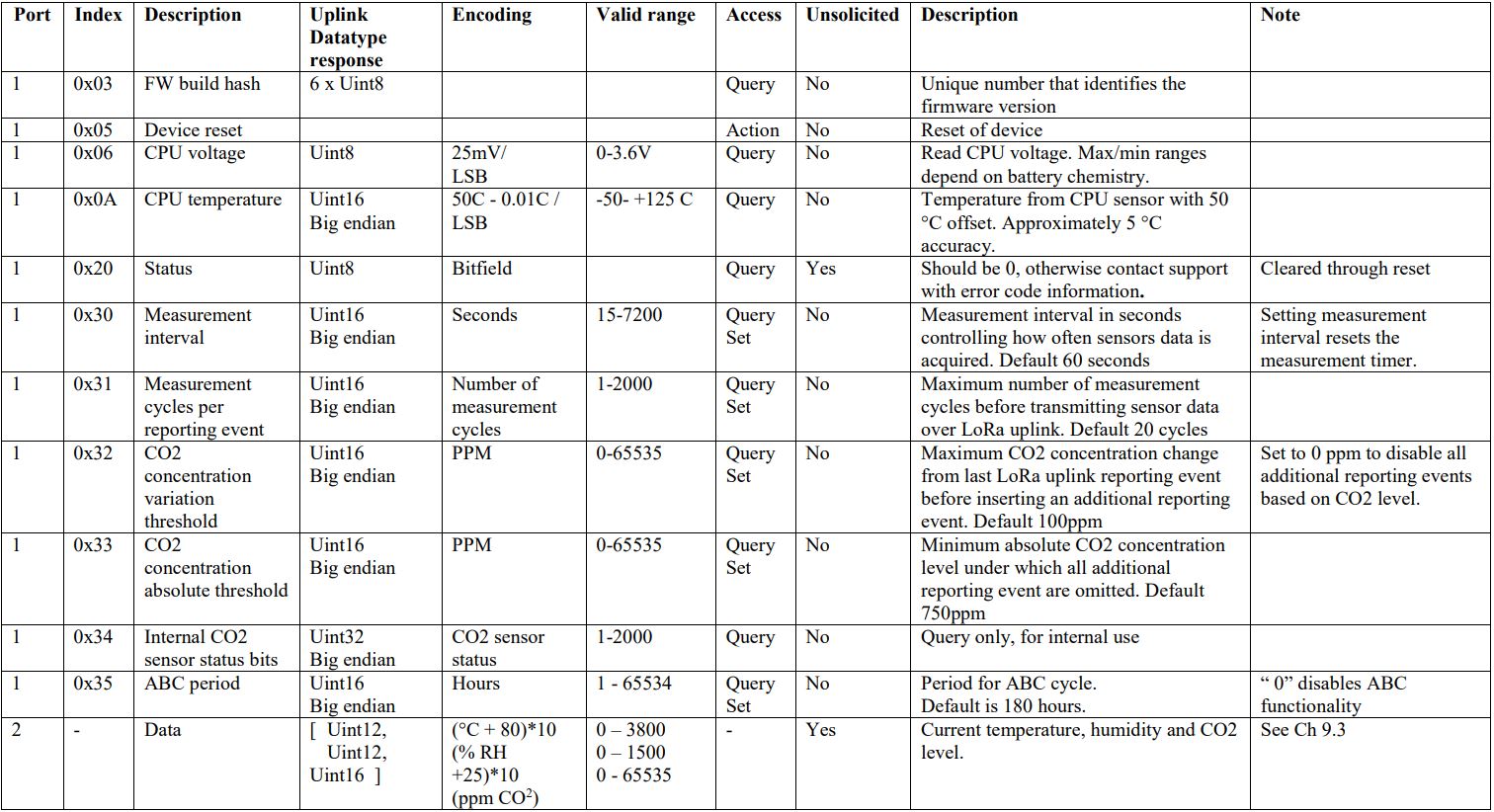
The temperature measurement is transmitted using an unsigned 12-bit value. The scaling is 1/10 °C and the offset is 80 °C, which means the received value should be subtracted by 800 and then divided with 10 to get it in °C.
10.3.2.2 Relative humidity conversion
The relative humidity (RH) measurement is transmitted using an unsigned 12-bit value. The scaling is 1/10 % RH and the offset is 25 % RH, which means the received value should be subtracted by 250 and then divided with 10 to get it in % RH.
10.3.2.3 Carbon dioxide (CO2) conversion
The carbon dioxide (CO2) measurement in parts-per-million (ppm 1 x 10⁻⁶). The CO2 data is averaged over a measurement period. The data is transmitted using an un-signed 16-bit integer. The value 0xFFFF indicates an error in the CO2 reading and should be displayed as an alarm or error code in the application, not as a measurement value.
10.3.3 Example: Single measurement report
Data sent on LoRaWAN port 2 : 3e 44 1d 02 1b
(3e1) HEX: (993) DEC => 993/10 -80°C => 19.3 gradC
(44d)HEX: (1101) DEC => 1101/10 – 25% => 85.1 % RH
(021b)HEX: (539) DEC => 539 ppm CO2
10.4 Downlink commands and queries
To control the sensor application, in-band commands and queries can be sent from the server application. Contact your LoRaWAN network provider for in-band application API. All downlink application communication is done on LoRaWAN port 1.

10.4.1 Reset device
The device can be reset by three methods, long press on button, removal of battery (note the device will be running for approximately 24 hours even without batteries), or forced into Joining state by OTA commands.
Example: Remote device reset:
Port 1: 0305
10.5 Uplink query response
Uplink messages are sent on port 1 with the following heading:

Example: Port 1: Payload 0x01 20 00
0x01: Data type
0x20: Status command
0x00: Normal startup
The expected behaviour is 0x01 20 00. If not contact support.
