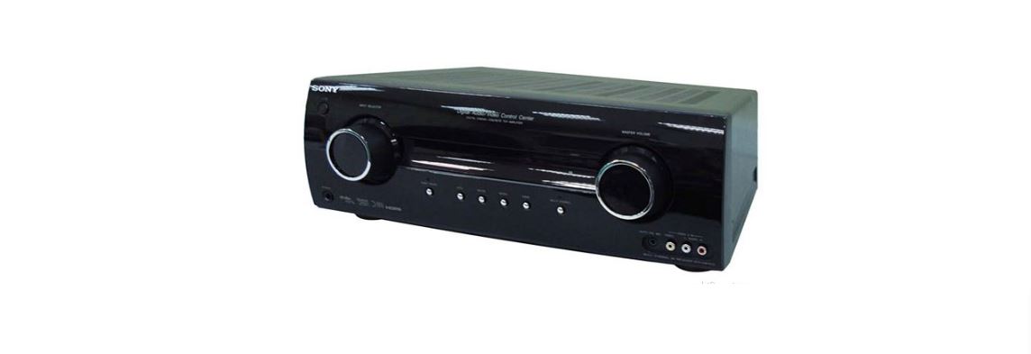
SONY STR-KM5500 Multi Channel AV

Receiver Owner's Manual
STR-KM5500
SECTION 7
EXPLODED VIEWS
Note:
- -XX and -X mean standardized parts, so they may have some difference from the original one.
- Items marked “*” are not stocked since they are seldom required for routine service. Some delay should be anticipated when ordering these items.
- The mechanical parts with no reference number in the exploded views are not supplied.
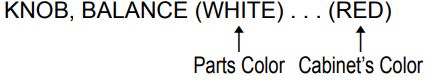
- Color Indication of Appearance Parts Example:
- Abbreviation
AR : Argentina model
E51 : Chilean and Peruvian models
EA : Saudi Arabia model
MY : Malaysia model
SAF : South African model
SP : Singapore model
The components identified by mark ![]() or dotted line with mark
or dotted line with mark ![]() are critical for safety. Replace only with part number specified.
are critical for safety. Replace only with part number specified.
7-1. CASE
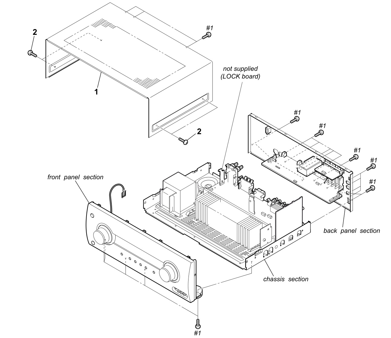
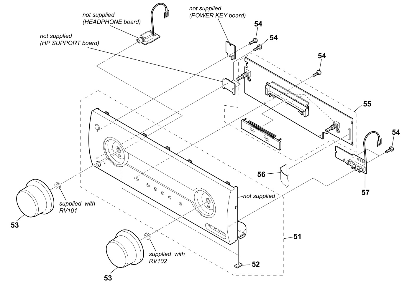
7-2. FRONT PANEL SECTION
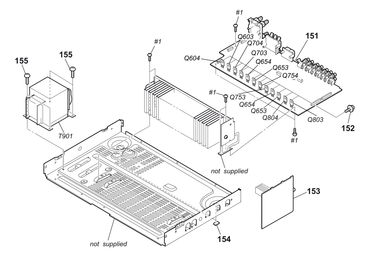
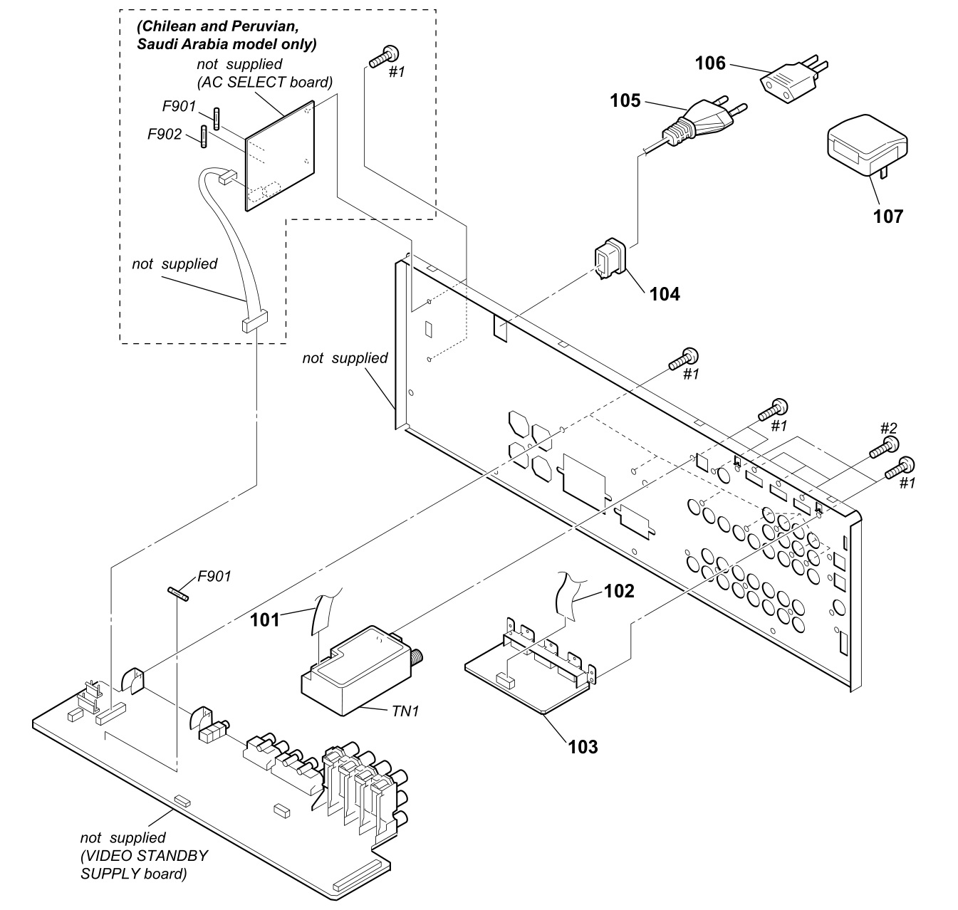
7-3. BACK PANEL SECTION
 Note: If connector, FFC is replaced, install it after bending it in the same form as that before replacement.
7-4. CHASSIS SECTION