PCE-HT 114 Temperature and Humidity Data
Logger User Manual
User manuals
Safety notes
Please read this manual carefully and completely before you use the device for the first time. The device may only be used by qualified personnel and repaired by PCE Instruments personnel. Damage or injuries caused by non-observance of the manual are excluded from our liability and not covered by our warranty.
- The device must only be used as described in this instruction manual. If used otherwise, this can cause dangerous situations for the user and damage to the meter.
- The instrument may only be used if the environmental conditions (temperature, relative humidity, …) are within the ranges stated in the technical specifications. Do not expose the device to extreme temperatures, direct sunlight, extreme humidity or moisture.
- Do not expose the device to shocks or strong vibrations.
- The case should only be opened by qualified PCE Instruments personnel.
- Never use the instrument when your hands are wet.
- You must not make any technical changes to the device.
- The appliance should only be cleaned with a damp cloth. Use only pH-neutral cleaner, no abrasives or solvents.
- The device must only be used with accessories from PCE Instruments or equivalent.
- Before each use, inspect the case for visible damage. If any damage is visible, do not use the device.
- Do not use the instrument in explosive atmospheres.
- The measurement range as stated in the specifications must not be exceeded under any circumstances.
- Non-observance of the safety notes can cause damage to the device and injuries to the user.
We do not assume liability for printing errors or any other mistakes in this manual.
We expressly point to our general guarantee terms which can be found in our general terms of business.
If you have any questions please contact PCE Instruments. The contact details can be found at the end of this manual.
Device description
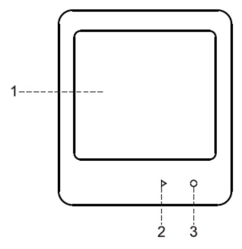
2.1 Front page
- : LC display
- : Start/stop key / display time
- : Switch display on/off / show data / mark
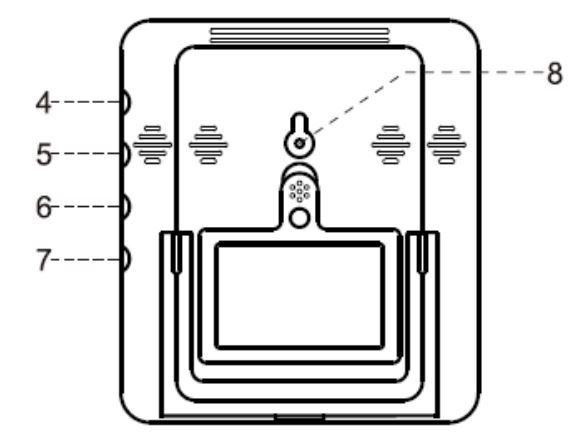
2.2 Backside
4: External sensor connection 1
5: External sensor connection 2
6: External sensor connection 3
7: External sensor connection 4
8: Reset key / mounting tab
![]() Note: The connections for external sensors may vary depending on the model.
Note: The connections for external sensors may vary depending on the model.
2.3 Display
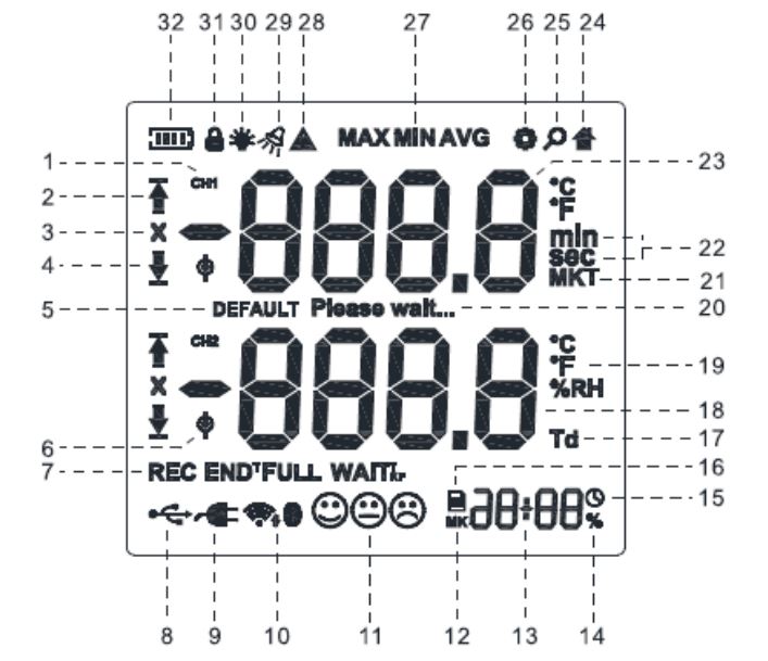
- : Channel number
- : Alarm exceeded
- : Alarm display
- : Alarm underrun
- : Factory reset
- : External sensor connected
- : Recording
- : USB connected
- : Data logger is being charged
- : Radio connection active (depending on model)
- : Air quality indicator
- : Marker
- : Time
- : Percentage symbol
- : Clock symbol
- : Memory symbol
- : Td: dew point
- : Lower measured value display
- : Temperature or humidity symbol
- : Waiting symbol
- : MKT: mean kinetic temperature1
- : Time unit
- : Upper measured value display
- : House symbol
- : Display symbol
- : Settings symbol
- : MIN / MAX / average display
- : Warning symbol
- : Buzzer symbol
- : Backlight
- : Keys locked
- : Battery status display
![]() Note: Certain icons may or may not be displayed depending on the model.
Note: Certain icons may or may not be displayed depending on the model.
1 The “mean kinetic temperature” is a simplified way to determine the overall influence of temperature fluctuations during the storage or transport of pharmaceuticals. The MKT can be regarded as an isothermal storage temperature that simulates the non-isothermal effects of changes in the storage temperature. Source: MHRA GDP
Technical specifications
3.1 Technical data PCE-HT 112
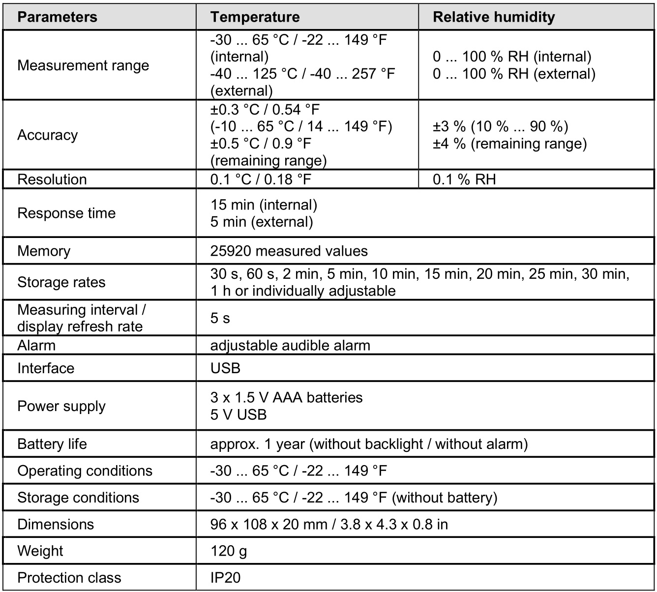
3.1.1 Scope of delivery PCE-HT 112
1 x data logger PCE-HT112
3 x 1.5 V AAA battery
1 x fixing set (dowel & screw)
1 x micro USB cable
1 x software on CD
1 x user manual
3.1.2 Accessories
PROBE-PCE-HT 11X external probe
3.2 Technical data PCE-HT 114
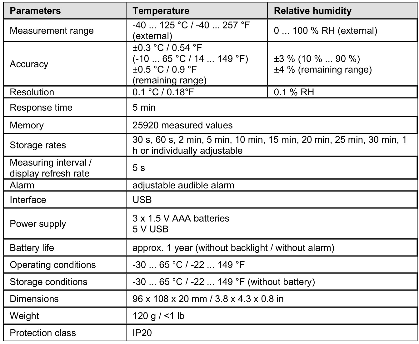
3.2.1 Scope of delivery PCE-HT 114
1 x refrigerator thermo hygrometer PCE-HT 114
1 x external sensor
3 x 1.5 V AAA battery
1 x fixing set (dowel & screw)
1 x micro USB cable
1 x software on CD
1 x user manual
3.2.2 Accessories
PROBE-PCE-HT 11X external probe
Operating instructions
If no key is pressed within 15 seconds, the automatic key lock is activated. Press the ![]() key for three seconds to make operation possible again.
key for three seconds to make operation possible again.
4.1 Switch on the device
The data logger switches on as soon as batteries are inserted into the device.
4.2 Switch off the device
The data logger is permanently switched on and switches off as soon as the batteries are no longer sufficiently charged to ensure proper operation.
4.3 Switch on the display
Press the ![]() key for three seconds and the display switches on.
key for three seconds and the display switches on.
4.4 Switch off the display
Press the ![]() key for three seconds and the display switches off.
key for three seconds and the display switches off.
![]() Note: The display cannot be turned off when it shows REC or MK.
Note: The display cannot be turned off when it shows REC or MK.
4.5 Switching the time / date
Press the ![]() key to switch between date, time and marker view.
key to switch between date, time and marker view.
4.6 Start data recording
Press the ![]() key for three seconds to start data recording.
key for three seconds to start data recording.
4.7 Stop data recording
If the software has been set to stop recording, press the ![]() key for three seconds to stop recording.
key for three seconds to stop recording.
Furthermore, recording stops when the memory is full or the batteries are no longer sufficiently charged to ensure proper operation.
4.8 Display minimum, maximum and average measured value
As soon as one or more measured values have been saved to the memory of the data logger, it is possible to display the MIN, MAX and average measured values by pressing the ![]() key.
key.
If no measured values are recorded, the ![]() key can be used to display the upper and lower alarm limits.
key can be used to display the upper and lower alarm limits.
4.9 Deactivate the audible alarm
As soon as an alarm is triggered and the meter beeps, the alarm can be acknowledged by pressing one of the two keys.
4.10 Set markers
Once the meter is in recording mode, you can switch to marker view by pressing the ![]() key. To set a marker, press the
key. To set a marker, press the ![]() key for three seconds to save a marker in the current recording. A maximum of three markers can be set.
key for three seconds to save a marker in the current recording. A maximum of three markers can be set.
4.11 Read out data
To read out data from the data logger, connect the measuring instrument to the PC and start the software. When the instrument is connected to the computer, the USB icon appears on the display.
Hints
5.1 External sensor
If the external sensor was not recognized, it may have been deactivated in the software. First activate the external sensor in the software.
5.2 Battery
When the battery icon flashes or the display shows OFF, this indicates that the batteries are low and need to be replaced.
Contact
If you have any questions, suggestions or technical problems, please do not hesitate to contact us. You will find the relevant contact information at the end of this user manual.
Disposal
For the disposal of batteries in the EU, the 2006/66/EC directive of the European Parliament applies. Due to the contained pollutants, batteries must not be disposed of as household waste.
They must be given to collection points designed for that purpose.
In order to comply with the EU directive 2012/19/EU we take our devices back. We either re-use them or give them to a recycling company which disposes of the devices in line with law.
For countries outside the EU, batteries and devices should be disposed of in accordance with your local waste regulations.
If you have any questions, please contact PCE Instruments.
![]()
PCE Instruments contact information
United Kingdom
PCE Instruments UK Ltd
Unit 11 Southpoint Business Park
Ensign Way, Southampton
Hampshire
United Kingdom, SO31 4RF
Tel: +44 (0) 2380 98703 0
Fax: +44 (0) 2380 98703 9
info@pce-instruments.co.uk
www.pce-instruments.com/english
United States of America
PCE Americas Inc.
711 Commerce Way suite 8
Jupiter / Palm Beach
33458 FL
USA
Tel: +1 (561) 320-9162
Fax: +1 (561) 320-9176
info@pce-americas.com
www.pce-instruments.com/us
© PCE Instruments
