SAFETY RULES
1. To reduce the risk of electric shock, insure electricity has been turned off at the circuit breaker or fuse box before beginning.
2. All wiring must be in accordance with the National Electrical Code and local electrical codes. Electrical installation should be performed by a qualified licensed electrician.
3. WARNING: To reduce the risk of fire or electric shock, do not use this fan with any solid-state speed control. Use only the control provided with the fan.
4. WARNING: To reduce the risk of personal injury, use only the two steel screws (and lock washers) provided with the outlet box for mounting to the outlet box. Most outlet boxes commonly used for the support of lighting fixtures are not acceptable for fan support and may need to be replaced, consult a qualified electrician if in doubt.

5. WARNING: To reduce the risk of fire, electric shock, or Personal Injury, mount directly to a structural framing member or to an outlet box marked ’Acceptable for Fan Support of 15.9 kg (35 lbs) or less’. For outlet box mounting, use mounting screws provided with the outlet box.
6. The fan must be mounted with a minimum of 7 feet clearance from the trailing edge of the blades to the floor.
7. To operate the reverse function on this fan, press the reverse button while the fan is running. A few seconds later the fan will slow to stop and then reverse direction.
8. Avoid placing objects in the path of the blades.
9. To avoid personal injury or damage to the fan and other items, be cautious when working around or cleaning the fan.
10. Do not use water or detergents when cleaning the fan or fan blades. A dry dust cloth or lightly dampened cloth will be suitable for most cleaning.
11. After making the electrical connections, spliced conductors should be turned upward and pushed carefully up into outlet box. The wires should be spread apart with the ground wire and white (common) wire to one side with the black (load) wire to the other side of the outlet box.
12. Electrical diagrams are reference only. Light kits that are not packed with the fan must be ETL Listed and marked suitable for use with the model fan you are installing. Switches must be ETL General Use Switches. Refer to the Instructions packaged with the light kits and switches for proper assembly.

TOOLS AND MATERIALS REQUIRED
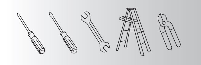
Philips screw driver
Blade screw driver
11 mm wrench
Step ladder
Wire cutters
PACKAGE CONTENTS
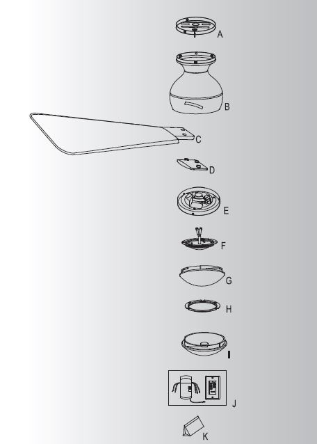
Unpack your fan and check the contents . You should have the following items:
A. Ceiling Mounting Plate/Bracket
B. Motor Assembly
C. Blade (3)
D. Blade Trim (3)
E. Switch Housing
F. LED Assembly
G. Glass Shade
H. Light Kit Wire Cover
I. Steel Cap
J. Wall Mount Control System
K. Package hardware
1) Mounting hardware: wood screws(2), flat washers (2), screws (2) , lock washers (2), wire nuts (3)
2) Blade attachment hardware: Screws (11)
3) Safety cable hardware : wood screw (1) , spring washer (1), flat washer (1)
4) Balance kit
MOUNTING OPTIONS


If there isn’t an existing ETL listed mounting box, then read the following instructions. Disconnect the power by removing fuses or turning off circuit breakers.
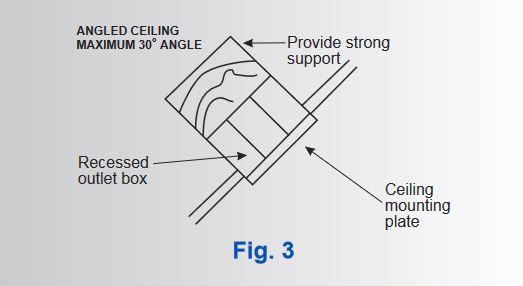
Secure the outlet box directly to the building structure. Use appropriate fasteners and building materials. The outlet box and its support must be able to fully support the moving weight of the fan (at least 50 lbs). Do not use plastic outlet boxes.
Figures 1, 2 and 3 are examples of different ways to mount the outlet box.
NOTE: If you are installing the ceiling fan on a sloped (vaulted) ceiling, you may need a longer downrod to maintain proper clearance between the tip of the blade and the ceiling. A minimum clearance of 12″ is suggested for optimal operation.
NOTE: Depending on the location you have selected for installation, you may need to purchase and install a “Joist Hanger” for the support of the outlet box. Make sure the joist hanger you purchase has been designed for use with ceiling fans. (Fig. 4)
HANGING THE FAN
REMEMBER to turn off the power before you begin installation. This is necessary for your safety and also the proper programming of the
control system.
To properly install your ceiling fan, follow the steps below.
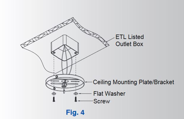
Step 1. Pass the 120 Volt supply wires from the ceiling outlet box through the center of the mounting bracket. Securely attach the Ceiling
Mounting Plate/Bracket to the ceiling junction box as shown. ( Fig. 4)
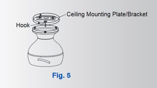 Step 2. Hook the motor body onto the Ceiling Mounting Plate/Bracket as shown. You can now proceed with the electrical wiring of your fan. (Fig. 5)
INSTALLATION THE SAFETY SUPPORT
A safety support cable is provided to help prevent the ceiling fan from failing, please install it as follows.

Step 1. Drive a wood screw and washers into the side of the brace that holds the outlet box. Leave 3mm (1/8″) of space between the support brace and the washer. (Fig. 6)
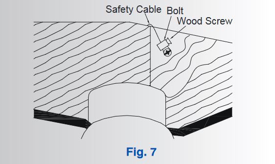
Step 2. Insert the safety cable through the mounting bracket and one of the holes in the outlet box into the ceiling. Adjust the length of the safety cable to reach the screw and washers by pulling the extra cable through the cable clamp until the overall lenght is correct, put the end of the cable back through the cabel clamp, forming a loop at the end of the cable. Tighten the cable clamp securely. Now, put the loop in the end of the safety cabel over the wood screw and under the washer. Tighten the wood screw securely. (Fig. 7)
NOTE: Although the safety support cable is required for Canadian installations only. It’s a good idea to make the attachment with any installation.
MAKE THE ELECTRIC CONNECTIONS
WARNING: To avoid possible electrical shock, be sure you have turned off the power at the main circuit panel before wiring.
Follow the steps below to connect the fan to your household wiring. Use the wire connecting nuts supplied with your fan. Secure the connector with electrical tape. Make sure there are no loose wire stands or connections.
WARNING: If your house wires are different colors than referenced in this manual, stop immediately. A professional electrician is recommended to determine proper wiring.
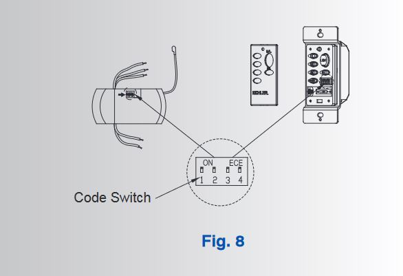
NOTE: The CoolTouch Control System is equipped with 16 code combinations to prevent possible interference from or to other remote units. The frequency switches on your receiver and transmitter have been preset at the factory. Please recheck to make sure the switches on the transmitter and receiver are set to the same position, any combination of settings will operate the fan as long as the transmitter and receiver are set to the same opposition. ( Fig. 8) Chainging the orfer of switches on each switch block, changes the operational frequency.

Step 1. Motor to Receiver Electrical Connections: Connect the BLACK wire from the fan to BLACK wire marked “TO MOTOT L” from the receiver. Connect the WHITE wire from the fan to the WHITE wire marked “TO MOTOR N” from the receiver. Connect the BLUE wire from the fan to the BLUE wire marked “FOR LIGHT” from the receiver. Secure all the wire connections with the plastic wire nuts provided. ( Fig. 9)
Step 2. Remote Receiver to Outlet Box Electrical Connections: Connect the BLACK (hot) wire from the ceiling to the BLACK wire marked “AC in L” from the receiver . Connect the WHITE ( neutral ) wire from the ceiling to the WHITE wire marked “ AC in N” from the Receiver . Secure the wire connections with the plastic wire nuts provided . ( Fig. 9)
Step 3. If your outlet box has a ground wire ( green or bare copper ) connect it to the fan ground wires : Secure the wire connection with a plastic nut provided. After connecting the wires, spread them apart so that the green and white wires are on one side of the outlet box and black wire is on the other side. ( Fig. 9)
NOTE: Carefully tuck the wire connections up into the outlet box.
NOTE: Fan must be installed at a maximum distance of 30 feet from the transmitting unit for proper signal transmission between the transmitting unit and the fan’s receiving unit.
FINISHING THE INSTALLATION

Step 1. Remove the 3 small screws from the motor assembly for later use. Lift up the motor housing on to the Ceiling Mounting Plate/Bracket, align the 3 holes from both parts. Secure the motor housing to the motor bracket by using the 3 small screws removed previously. (Fig. 10)
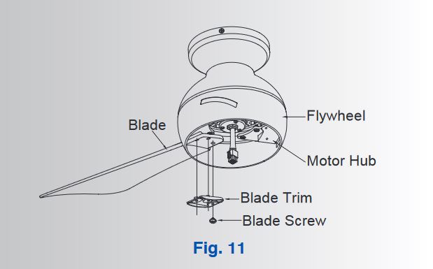
Step 2. Insert the blade through the slots on theflywheel and attach to the motor hub using the blade screws and blade tirm. Make sure the screws securing the blades to the motor hub are tighten and are properly seated. (Fig. 11)
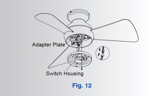
Step 3. Remove one of the three screws in the adapter plate at the bottom of the motor assembly and retain the screw for later use. Slightly loosen the remaining two screws. Place the motor connector through the center hole of the switch housing. Rotate the switch housing key hole slots clockwise to engage both loosened screws. Reinstall the previous removed screw. Secure the switch housing to the adapter plate by tightening the three screws.(Fig. 12)

Step 4. Remove one of the three screws in the switch housing. Slightly loosen the remaining two screws. (Fig. 13)
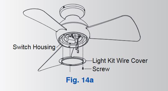
Step 5. If installing the light kit, skip to step 7. Assembly the light kit wire cover to the switch
housing using the two key slots. Replace the removed screw and secure all three screws. (Fig. 14a)
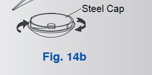
Step 6. Assemble the steel cap to the light kit bytwisting in a clockwise direction. (Fig. 14b)
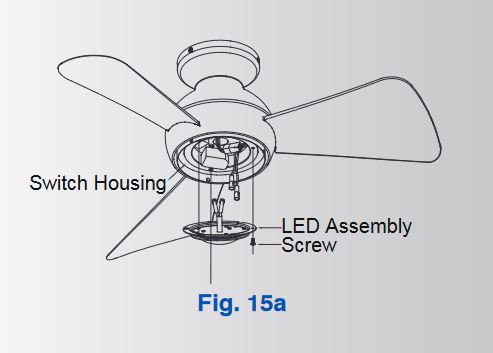
Step 7. for use with light kit Connect the 2single-pin connectors from the switch housing to the 2 single-pin connectors from LED assembly. Assemble the LED assembly to the switch housing using the two key slots. Replace the third screw removed in step 4 and securely tighten all three screws. (Fig. 15a)

Step 8. Secure the glass shade to switch housing bytwisting in a clockwise direction. Do not over-tighten. (Fig. 15b)
INSTALLING THE TRANSMITTER

All wiring nust be in accordance with the NationalElectrical Code and local electrical codes. Electrical installation should be performed by a qualified licensed electrician.
Select a location to install your wall mount Control System Transmitter. You can replace an existing wall seitch, or install the transmitter to a new outlet box.
NOTE: Make sure the electrical power is TURNED OFF at the main panel before continuing.
NOTE: SWITCH INSTALLATION MUST COMPLY WITH ALL LOCAL AND NATIONAL ELECTRIC CODE.
Step 1. Remove the existing wall plate and the old switch from the wall outlet box. Wire nut the BLACK leads (hot) together and push back inside the outlet box. (Fig. 16) Or Select the desired location with a new wall outlet box.
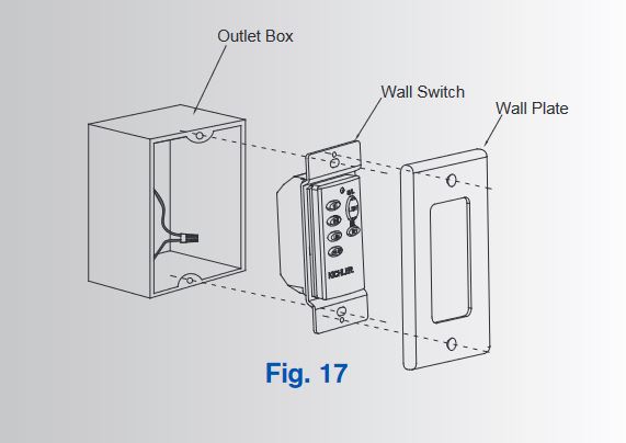
Step 2. Use the screws provided to secure the wall transmitter to the outlet box. (Fig. 17)
CONTROL SYSTEM SET-UP

NOTE: Make sure the power is completely disconnected before you begin this procedure.
Read all of these steps before preceeding. Each step must be followed exactly to properly program the control system.
Step 1. Use a small flat screw driver and gently pry it apart from the top or bottom of the switch plate. Install 1, 12volt battery included with wall mount Control system and make sure it is seated correctly. Replace the switch plate. Fig. 18)
Step 2. Test the transmitter by pressing and releasing ANY button. A RED Light should illuminate, if not, check to make sure the battery
is inserted and seated correctly. (Fig. 18)
NOTE: To prevent damage to transmitter , remove the battery if not used for long periods of time ( months ).
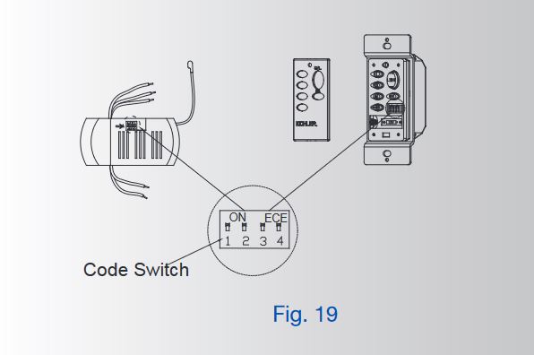
Step 3. You can leave the frequency switches at the factory setting. Or you have to change the dip switch setting in the remote if you are using more than one fan in the same area and want to control them separately. Remove the battery and change the dip switch setting,
assuring that they are different from the other fans. Reinstall the battery and switch plate on the control. (Fig. 19)
OPERATING INSTRUCTIONS:

Restore power to ceiling fan and test for proper operation (Fig. 20)
1. Fan Control: To start the fan. Press the selected speed button to run the fan at the desired speed: Hi-high; MED-medium; LOW-low;
To turn off the fan. Press the “OFF” button.
2. Light On/Off-press and release light button.
3. Light Dimmer-continuous pressure on the light button dims light in a continuous cycle from light to dark, or dark to light.
4. Fan Reverse – controls direction, forward or reverse.
Speed setting for warm or cool weather depend on factor such as the room size, ceiling height, number of fans and so on.
Warm Weather Operation:
Forward (counterclockwise) A downward airflow creates a cooling effect . This allows you set your air conditioner on a warmer setting without affecting your general comfort.
Cool Weather Operation: Reverse (clockwise) An upward airflow creates a warm air off the ceiling areas. This allows you set your air conditioner on a cooler setting without affecting your general comfort.
TROUBLESHOOTING
Problem: Fan will not start.
Solution: 1. Check circuit fuses or breakers.
2. Check all electrical connections to insure proper contact. CAUTION: Make sure the main power is OFF when checking any electrical connection.
3. Make sure the transmitter batteries are installed properly. Positive (+) sidefacing out.
4. Insure the batteries have a good charge.
Problem: Fan sounds noisy.
Solution: 1. Make sure all motor housing screws are snug.
2. Make sure the screws that attach the fan blade brackets to the motor are tight.
3. Make sure wire nut connections are not rubbing against each other or the interior wall of the switch housing. CAUTION: Make sure main power is off.
4. Allow a 24-hour “breaking-in” period. Most noise associated with a new fan disappear during this time.
5. If using an optional light kit, make sure the screws securing the glassware are tight. Make sure the light bulbs are not touching any other component.
6. Do not connect this fan to a wall mounted variable speed control(s). They are not compatible with ceiling fan motors or remote controls.
7. Make sure the upper canopy is a short distance from the ceiling. It should not touch the ceiling.
Problem: Fan wobble.
Solution: 1. Check that all blade and blade arm screws are secure.
2. Most fan wobbling problems are caused when blade levels are unequal. Check this level by selecting a point on the ceiling above the tip of one of the blades. Measure this distance. Rotate the fan until the next blade is positioned for measurement. Repeat for each blade. The distance deviation should be equal within 1/8″.
3. Use the enclosed Blade Balancing Kit if the blade wobble is still noticeable.
4. If the blade wobble is still noticeable, interchanging two adjacent (side by side) blades can redistribute the weight and possibly result in smoother operation.
Problem: Remote control malfunction.
Solution: 1. Ceiling Fans with remote control systems CAN NOT be operated inconjunction with any other control system EXCEPT a basic On/Off wall switch, if desired.
FCC WARNNING:
This device complies with part 15 of the FCC Rules. Operation is subject to the folioeing two conditions:
(1) This device may not cause harmful interference, and (2) this device must accept any interferencereceived, including interference that may cause undesired operation.
Changes or modifictons not expressly approved by the party responsible for compliance could void the
user’s authority to operate the equipment.
NOTE: This equipment has been tested and found to comply with the linits for a Class B sidital device, pursuant to part 15 of the FCC Rules. These limits are designed to provide reasonable protection against harmful interference in a residential installatio. This equipment generates, uses and can rediate tadio frequency energy and, if not installed and used in accordance with the instructions, may cause harmful interference to radio communications. However, these is no guarantee that interference will not occur in a particular installation. If this rquipment dose cause harmful interfence to radio or twlwvision reception, which can be determined by turning the equipment off and on, the user is encouraged to try to correct the interference by one or more of the following measures:
Reorient or relocate teh receiving antenna, increase the separation between the equipment and receiver, and connect the equipment into an outlet on a circuit different from that no which the fan is connected.
SPECIFICATIONS
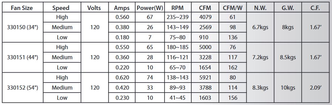
These are approximate measures . They do not include data for any lamps or fixtures attached to the ceiling fan.