LINORTEK ONEYEAR LIMITED WARRANTY
Consumer law: For consumers who are covered by consumer protection laws or regulations in their country of residence (“Consumer Law”), the benefits provided in this Linortek OneYear Limited Warranty (“Linortek Limited Warranty”) are in addition to and not instead of the rights provided by Consumer Law and it does not exclude, limit or suspend your rights arising from Consumer Law. You should consult the proper authorities in your country of residence for further information about these rights.
Linortek’s warranty obligations for this hardware product (“Product”) are
limited to the terms set forth below:
Linor Technology, Inc. (“Linortek”) warrants this product against defects in materials and workmanship for a period of ONE (1) YEAR from the date of retail purchase by the original enduser purchaser (“Warranty Period”) when used in accordance with the operating instructions. A copy of a retail receipt is required as proof of purchase. If a hardware defect arises and a valid claim is received within the Warranty Period, at its option and to the extent permitted by law, Linortek will either (1) repair the hardware defect at no charge, using new or refurbished replacement parts, (2) exchange the product with a product that is new or which has been manufactured from new or serviceable used parts and is at least functionally equivalent to the original product, or (3) refund the purchase price of the product. When a refund is given, the product for which the refund is provided must be returned to Linortek and becomes Linortek’s property.
The foregoing warranty is subject to Buyer’s (i) prompt written claim and (ii) timely provision to Linortek of an opportunity to inspect and test the Product claimed to be defective. Such inspection may be on Buyer’s premises and/or Linortek may request the return of the Product at Buyer’s expense. However, Linortek shall not be responsible for packing, inspection, or labor costs in connection with the return of Product. No Product shall be accepted for warranty service that is not accompanied by a Return Merchandise Authorization number (RMA#) issued by Linortek.
EXCLUSIONS AND LIMITATIONS
This Limited Warranty excludes damage resulting from abuse, misuse, neglect, fire or other external causes, accident, modifications, repairs or other causes that are not defects in materials and workmanship. Software distributed by Linortek with or without the Linortek brand name including, but not limited to system software (“Software”) is not covered under this Limited Warranty. Your use and rights associated with the Software are governed by the Linortek End User License Agreement which you can find here: https://www.linortek.com/enduserlicenseagreement/. Linortek is not responsible for damage arising from failure to follow instructions relating to the product’s use. To assure conformance with operating limitations, Buyer should refer to the instruction manual [provided with the product]. Batteries are not included in the Warranty.
TO THE MAXIMUM EXTENT PERMITTED, THIS LIMITED WARRANTY AND THE REMEDIES SET FORTH ABOVE ARE EXCLUSIVE AND IN LIEU OF ALL OTHER WARRANTIES, REMEDIES, AND CONDITIONS, AND LINORTEK SPECIFICALLY DISCLAIMS ALL STATUTORY OR IMPLIED WARRANTIES, INCLUDING BUT NOT LIMITED TO, WARRANTIES OF MERCHANTABILITY, FITNESS FOR A PARTICULAR PURPOSE, NONINFRINGEMENT. IN SO FAR AS SUCH WARRANTIES CANNOT BE DISCLAIMED, ALL SUCH WARRANTIES SHALL, TO THE EXTENT PERMITTED BY LAW, BE LIMITED IN DURATION TO THE DURATION OF THE LINORTEK LIMITED WARRANTY AND THE REMEMDY SHALL BE LIMITED TO REPAIR, REPLACEMENT OR REFUND AS DETERMINED BY LINORTEK IN ITS SOLE DISCRETION. SOME STATES (COUNTRIES AND PROVINCES) DO NOT ALLOW LIMITATIONS ON HOW LONG AN IMPLIED WARRANTY OR CONDITION MAY LAST, SO THE LIMITATIONS
DESCRIBED ABOVE MAY NOT APPLY TO YOU. THIS WARRANTY GIVES YOU SPECIFIC LEGAL RIGHTS, AND YOU MAY ALSO HAVE OTHER RIGHTS THAT VARY FROM STATE TO STATE (OR BY COUNTRY OR PROVINCE). THIS LIMITED WARRANTY IS GOVERNED BY AND CONSTRUED UNDER THE LAWS OF THE UNITED STATES.
- Read Instructions All the safety and operating instructions should be read before the unit is operated.
- Retain Instructions The safety and operating instructions should be retained for future reference.
- Heed Warnings All warnings on the unit and in the operating instructions should be adhered to.
- Follow Instructions All operating and use instructions should be followed.
- Cleaning Unplug the unit from power before cleaning. Do not use liquid cleaners or aerosol cleaners. Use a damp cloth for cleaning.
- Attachments Do not use attachments not recommended by them product manufacturer as they may cause hazards.
- Accessories Do not place this unit on an unstable stand, tripod, bracket, or mount. The unit may fall, causing serious injury to a person and serious damage to the unit. Use only with a stand, tripod, bracket, or mount recommended by the manufacturer, or sold with the product. Any mounting of the unit should follow the manufacturer’s instructions, and should use a mounting accessory recommended by the manufacturer. An appliance and cart combination should be moved with care. Quick stops, excessive force, and uneven surfaces may cause the appliance and cart combination to overturn.
- Ventilation Openings in the enclosure, if any, are provided for ventilation and to ensure reliable operation of the unit and to protect it from overheating. These openings must not be blocked or covered. This unit should not be placed in a builtin installation unless proper ventilation is provided or the manufacturer’s instructions have been adhered to.
- Power Sources This unit should be operated only from the type of power source indicated on the marking label. If you are not sure of the type of power supply you plan to use, consult your appliancem dealer or local power company. For units intended to operate from battery power, or other sources, refer to the operating instructions.
- Grounding or Polarization This unit may be equipped with a polarized alternatingcurrent line plug (a plug having one blade wider than the other). This plug will fit into the power outlet only one way. This is a safety feature. If you are unable to insert the plug fully into the outlet, try reversing the plug. If the plug should still fail to fit, contact your electrician to replace your obsolete outlet. Do not defeat the safety purpose of the polarized plug. Alternately, this unit may be equipped with a 3wire groundingtype plug, a plug having a third (grounding) pin. This plug will only fit into a groundingtype power outlet. This is a safety feature. If you are unable to insert the plug into the outlet, contact your electrician to replace your obsolete outlet. Do not defeat the safety purpose of the groundingtype plug.
- PowerCord Protection Powersupply cords should be routed so that they are not likely to be walked on or pinched by items placed upon or against them, paying particular attention to cords and plugs, convenience receptacles, and the point where they exit from the appliance.
- Power Lines An outdoor system should not be located in the vicinity of overhead power lines or other electric light or power circuits, or where it can fall into such power lines or circuits. When installing an outdoor system, extreme care should be taken to keep from touching such power lines or circuits as contact with them might be fatal.
- Overloading Do not overload outlets and extension cords as this can result in a risk of fire or electric shock.
- Object and Liquid Entry Never push objects of any kind into this unit through openings as they may touch dangerous voltage points or shortout parts that could result in a fire or electric shock. Never spill liquid of any kind on the unit.
- Servicing Do not attempt other service to this unit yourself as opening or removing covers may expose you to dangerous voltage or other hazards. Refer all other servicing to qualified service personnel.
- Damage Requiring Service Unplug the unit from the outlet and refer servicing to qualified service personnel under the following conditions:
a. When the powersupply cord or plug is damaged.
b. If liquid has been spilled, or objects have fallen into the unit.
c. If the unit has been exposed to rain or water.
d. If the unit does not operate normally by following the operating instructions. Adjust only those controls that are covered by the operating instructions, as an improper adjustment of other controls may result in damage and will often require extensive work by a qualified technician to restore the unit to its normal operation.
e. If the unit has been dropped or the cabinet has been damaged.
f. When the unit exhibits a distinct change in performance this indicates a need for service. - Replacement Parts When replacement parts are required, be sure the service technician has used replacement parts specified by the manufacturer or have the same characteristics as the original part. Unauthorized substitutions may result in fire, electric shock or other hazards.
- Safety Check Upon completion of any service or repairs to this unit, ask the service technician to perform safety checks to determine that the unit is in proper operating condition.
- Coax Grounding If an outside cable system is connected to the unit, be sure the cable system is grounded. U.S.A. models only Section 810 of the National Electrical Code, ANSI/NFPA No.701981,
- provides information with respect to proper grounding of the mount and supporting structure, grounding of the coax to a discharge unit, size of grounding conductors, location of discharge unit, connection to grounding electrodes, and requirements for the grounding electrode.
- Lightning For added protection of this unit during a lightning storm, or when it is left unattended and unused for long periods of time, unplug it from the wall outlet and disconnect the cable system. This will prevent damage to the unit due to lightning and powerline surges.
- Outdoor Use This unit is not waterproof and should not be allowed to get wet. Do not expose to rain. Do not leave outofdoors overnight as condensation may occur.
- While changing batteries, fuses or handling a board level product be careful of electrostatic discharge which can damage electronic devices. It is best to use a grounded electronics service bench. If this is not available you can discharge yourself by touching a metal appliance or pipe. While changing the batteries or fuse do not touch
i) any wires other than the battery wires and ii) the printed circuit board.
DISCLAIMER FOR CRITICAL APPLICATIONS
This product is not intended or authorized for life support product or for other uses for which a failure could cause personal injury or death. If you or your customers use or permit the use of this product for such unintended or unauthorized uses, you agree to fully indemnify Linor Technology and its affiliates, and the officers, employees and distributors of each, from all liability related to such use, including attorneys’ fees and costs.
This product contains SOFTWARE and is provided by THE PROVIDER “as is” and “with all faults.” THE PROVIDER makes no representations or warranties of any kind concerning the safety, suitability, lack of viruses, inaccuracies, typographical errors, or other harmful components of this SOFTWARE PRODUCT. There are inherent dangers in the use of any software and THE PROVIDER will not be liable for any damages you may suffer in connection with using, this SOFTWARE PRODUCT.
 LIMITATION OF LIABILITY
IN NO EVENT WILL LINOR TECHNOLOGY BE LIABLE, WHETHER IN CONTRACT,n TORT, OR OTHERWISE, FOR ANY INCIDENTAL, SPECIAL, INDIRECT, CONSEQUENTIAL OR PUNITIVE DAMAGES, INCLUDING, BUT NOT LIMITED TO, DAMAGES FOR ANY LOSS OF USE, LOSS OF TIME, INCONVENIENCE, COMMERCIAL LOSS, OR LOST PROFITS, SAVINGS, OR REVENUES TO THE FULL EXTENT SUCH MAY BE DISCLAIMED BY LAW.
FURTHER NOTICE FOR LIMITATION OF USE
Unless specifically stated, this product is NOT designed to switch line voltage devices. This limitation includes all of Linortek products. To control device that operate at line voltages the user MUST install and intermediary device such as a relay. When choosing devices to control, it is best to select low voltage devices. When wiring a line voltage device, you MUST either be a qualified electrician or use the services of a qualified electrician. Additionally, local codes must be followed including but not limited to wire gauge size and suitable housing. Linortek cannot assume any responsibility for harm to the user or third parties for improperly using our Fargo product. This liability remains with the user. Linortek cannot assume any responsibility for damage to the device for improperly using our SERVER product. To prevent risk of electric shock causing injury, death, or damage to equipment; ensure power to equipment is shut off at the CIRCUIT BREAKER. If installing on a vehicle, ensure the vehicle’s battery is disconnected. Installation should be performed by a qualified technician or electrician.
RELAY VOLTAGE SPECIFICATIONS
Please use caution when connecting devices. This web controller is NOT designed to connect to any voltage greater than 48V. If you want the unit to control Line Voltage products and devices, refer to Diagram 1 below. Utilizing this arrangement, should allow you to virtually control anything. It is important that you use licensed electricians and comply with electrical codes that are applicable to your location. These codes exist for your safety, as well as the safety of others. Linortek cannot assume any responsibility for any harm or damage caused by not following specified instructions for installation and product usage.
THIS MANUAL
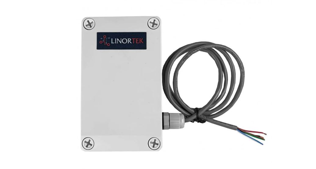
This manual covers: iTrixxWFMNDi, iTrixxWFMNADi units. These will be referred to as SERVER hereafter. When there are differences or additional features they will be noted in the text.
WHAT’S IN THE BOX
Please inspect the contents of your product kit. Each SERVER is sent in its own box and includes:
____One iTrixx WFMN SERVER
____One 12VDC Power Supply
____2 Wago Connectors
____One 2.2k Ohm Resistor Kit
____iTrixx WFMN Quick Setup Instruction
For instructional videos, FAQ’s and contact information for our technical support team, please visit: https://www.linortek.com/technicalsupport
To download the full manual, please go to our website Download page: https://www.linortek.com/downloads/documentations/
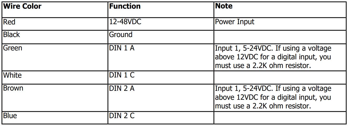
ITRIXXWFMN WIRE CHART
There is 1 cable on the iTrixxWFMNDi, and 3 cables on the iTrixxWFMNADi. From the top to bottom, they are marked as cable 1, 2, 3. See the chart below for explanation.

Cable 1: Analog Inputs (for iTrixxWFMNADi only)

Cable 2: Relay Outputs (for iTrixxWFMNADi only)

Cable 3: Digital Inputs and Power Input
BOARD REFERENCE LAYOUT
Below are bare board photos of your iTrixx Server. The terminal connectors come prewired for power, digital input, and analog input.
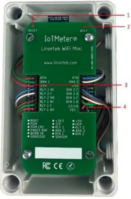 Reset Button
- DFLT Button
- Terminal Connector
- Terminal Connector
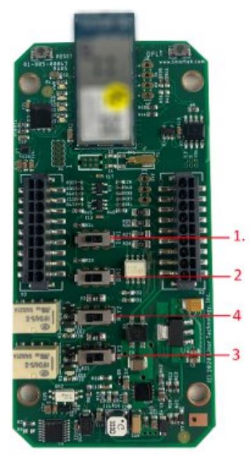
- Digital Input 1 Switch – Left for Pullup (PU), right for Isolated (ISO) (PU by default)
- Digital Input 2 Switch – Left for Pullup (PU), right for Isolated (ISO) (PU by default)
- Relay 1 Switch – Left +5VDC, right dry contact (5VDC by default)
- Relay 2 Switch – Left +5VDC, right dry contact (5VDC by default)
FACTORY RESET
Factory reset switch: For various reasons, you might want to reset your SERVER to factory default, you need to use the RESET and DFLT button to do the resetting. To reset the SERVER to its factory defaults, first to push the RESET button and the RED LED should blink while the GREEN LED is on. While in this state (called Bootload state) press and hold the DFLT button (about 10 15seconds) until the RED LED comes on steady (blinks at 1 second rate).
There is an equivalent FACTORY RESET function in the Telnet command that you can reset the Server to factory default: factory_reset.
ACTIVATE THE METER
The ITrixxWFMN is designed to be integrated into existing equipment to monitor runtime. Installing your iTrixx will involve tapping circuits on the equipment you intend to monitor.
The iTrixx Hour Meter has two separate hour counters. The hour counters may be activated in a number of different ways.
- In the simplest setup the iTrixx may be activated whenever power is applied to the unit. In this case, if the iTrixx is on, it is counting. A voltage threshold is provided so the iTrixx may stop counting as power is lost to prevent memory corruption. In this way, you only need to connect the iTrixx to the same power source of the equipment you wish to collect running data, no other wiring required.
- You may also use one of the inputs to turn counting on and off. There are two digital inputs in the iTrixx. The digital inputs allow iTrixx to detect an external on/off state of a sensor.
To use the meter on a mobile equipment, a constant 1248VDC power source from a battery, and a separate 548VDC circuit that turns on and off with the vehicle. A constant power source is preferable to power your Wifi meter because it will always be on. If the meter has to boot up when your equipment is powered on, you may not have an accurate reading. The WiFi meter at idle draws approximately 70mA. It will not drain the battery unless it is left for an exceptionally long time. - Alternatively, it can be configured to follow one of the relays such that when the relay is activated the iTrixx will count (for iTrixxWFMNADi unit only). The relays on the iTrixxWFMNADi are dry contact relays and normally open.
Most common use case is to wire a digital input to the same power source of your iTrixx Server to trigger the meter, so when your equipment is on, iTrixx is counting.
MAKE CONNECTIONS
Relay Connection (iTrixxWFMNADi)
Your iTrixxWFMNADi server has two 5VDC relay outputs. These relays are limited to a 5V signal and are prewired to the outside of the enclosure. There are 3 positions on the terminal NO (Normally Open), C (Common), and NC (Normally Closed). Additionally, there is a switch for each relay on the board. For a dry contact relay, push the switch to the right, to drive a 5VDC
signal, push the switch to the left. (See Board Layout Reference section to locate the relay output wires).
A note of CAUTION: These units are ground isolated. Always connect so that power loop is only connected to theiTrixx unit. Do NOT use external ground connections. Doing so may damage the SERVER or POE originating device.
Digital Inputs Connection
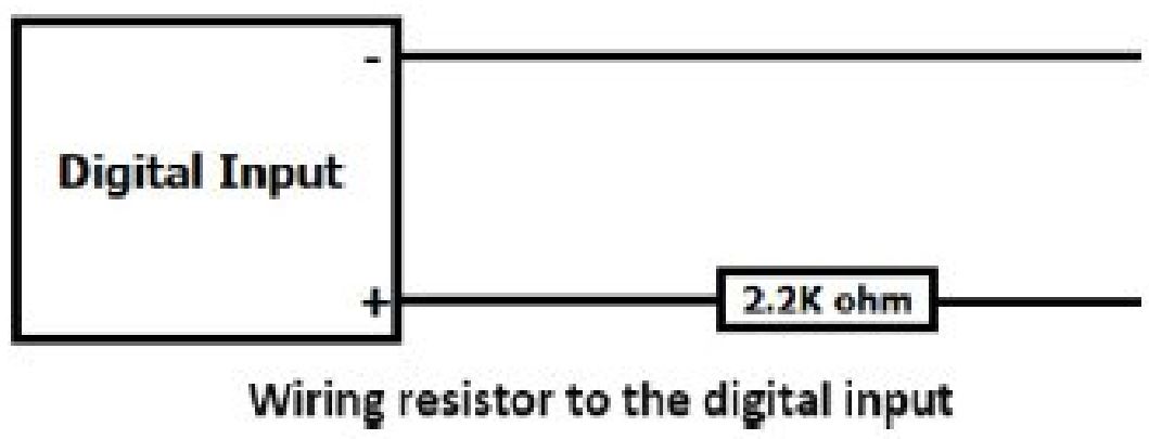
iTrixx servers have 2 digital inputs (524VDC) builtin to the board. The digital inputs allow the SERVER to detect an external on/off state of a sensor. With this information the SERVER can display whether an input is on or off, count events in a resettable or nonresettable counter, and calculate the frequency (such as for use as a tachometer) or the period of the input. See Board Reference Layout page to locate the digital input wires. A circuit that switches on and off with your equipment can be wired to this digital input to detect whether or not your machine is running. Note: If using a circuit above 12VDC you must include a 2.2k ohm resistor between the tapped circuit and the iTrixx. The iTrixx will only detect a voltage on this circuit and will not draw any power or interfere with this circuit. Do NOT exceed 24VDC on your digital input. Once wired, see the section Setup Triggers to trigger the hour counter or set up notifications. For how to use a resistor for the digital input, please refer to the diagram below:
There are two modes of operation for the digital inputs: ISOLATED and PULL UP. These are set at the factory to PULL UP by default.
1) ISOLATED mode allows you to directly drive the iTrixx’s optoisolator with an external voltage though an internal 1K resistor. This voltage may be in the range of 5VDC to 24VDC supplying a minimum of 2mA or a maximum of 30mA to the
optoisolator diode. There is no other internal connection to this voltage so it is an isolated input. The DIN in this mode will default to a Low state. To set this mode, move the DIN switch to the right (Towards center of board).
2) PULLUP mode connects a 1K resistor to an internal voltage allowing you to use a simple switch (such as a magnetic door switch) across terminals 1 and 2. When the switch is activated a signal is sent to the input. These modes are selected by the switch on the server (see the Board Layout for reference). The DIN in this mode will default to a High state. To set this mode, move the DIN switch to the Left (Towards edge of board).
Caution: If you intend to use isolated mode, verify input switch is set to ISO before applying an external voltage. Doing otherwise may damage the SERVER or POE originating device.
To wire your equipment to the iTrixx’s digital input, identify a circuit of 5 – 24VDC that switches on and off with your equipment. Wire this to DIN 1 or DIN 2 on your iTrixx.
Analog Inputs Connection (iTrixxWFMNADi)
The analog inputs allow the SERVER to read the value of external equipment. iTrixxWFMNADi has 2 analog inputs (5v 420mA) built in to the board. The 2 analog input wires are connected to nonisolated 05V current sensors which may be connected to a variety of devices such as temperature or pressure sensors. The SERVER provides a ground and power connection so that measurements can be made without external voltage references. You should use a sensor that is isolated so that the it makes no connection to a remote ground. This information can be set to trigger a notification. There are 3 wires for each analog input, see Board Reference Layout page to locate the analog input wires.
A note of CAUTION: These units are ground isolated. Always connect so that power loop is only connected to the iTrixx unit. Do NOT use external ground connections. Doing so may damage the SERVER or POE originating device.
Once you are finished wiring the iTrixx to your equipment, you may then power on your equipment or reconnect the vehicle’s battery and configure your device.
CONNECT TO YOUR NETWORK
- Before powering up the iTrixx
To configure your iTrixx, you will need the following information during the setup process, we suggest you to gather that information before putting your device in Provissioning Mode, because once you put your device in Provisioning Mode, you will have 2 minutes to connect it to your network before this mode times out.
1) Your network name and your WiFi password.
2) Write down the last 6 characters of your device’s MAC address, this will be the password to login to your iTrixx server when you config the software on Telnet. You can find the MAC address at the back of your device.
3) Use Telnet client for initial setup of your iTrixx device. To use Telnet on Windows 8.1 or Windows 10, follow the steps below:
• Open Control Panel
• Select Programs
• Under Programs and Features select Turn Windows features on or off
• Scroll down and select the checkbox for Telnet Client and click OK
4) Use your web browser to connect the iTrixx Server to your network. Since the iTrixx config page is not encrypted,you need to change the privacy & security settings on your browser. Here are some samples how to change your browser settings in order to connect to the config page:
• On Google Chrome, you can go to SettingsPrivacy and SecuritySafe Browsing, select No Protection.
• On Firefox, go to Privacy & Security Setting, scroll down to the page, on HTTPSOnly Mode, select Don’t Enable HTTPSOnly Mode.
• For other browsers, you can add wifihmconfig.com to your browser unprotected site so that you can access the config page.
5) Download the HourCollector desktop App from our website download page, this free tool can help you to find the IP address on your network, as well as for data collection/monitoring. Before downloading, ensure your computer has Java installed. Java is available for download here: https://www.java.com/en/. The Hour Collector app will automatically locate your iTrixx and allows for quick access. The Hour Collector app will not immediately locate the iTrixx if not connected via Ethernet. The iTrixx will appear once the HourCollector updates after receiving data from iTrixx devices. The HourCollector app updates every two minutes by default. You can download this tool here: https://www.linortek.com/downloads/supportprogramming/ - Powering iTrixx
Your iTrixx server is supplied with a 12VDC power supply. You may power your iTrixx server using this power supply for initial setup and software configuration. Once your initial setup is completed, you can wire your iTrixx to your equipment by tapping into a 12 – 48 VDC circuit on your equipment.To connect iTrixx to the 12VDC power supply, connect the RED wire on Cable 3 to the positive wire of the power supply, BLACK wire on Cable 3 to the negative wire (marked with white strip) on the power supply. Once powered, your iTrixx server is ready to be connected to your network. - Connecting iTrixx to WiFi Network
To connect the iTrixx to your network, follow the steps below:
1) Open the cover of the iTrixx, locate the DFLT button, push and hold the DFLT button with a paper clip until the blue LED starts flashing. Your device is now in Provisioning Mode. You have 2 minutes to configure connect to your network before this mode times out. Once the Provisioning mode times out, you will need to repeat the first step and put it in Provisioning mode.
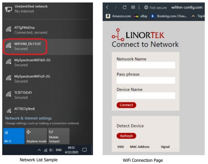
2) Use a WiFi enabled PC or a mobile device to connect to your server’s AP (WiFi enabled device is only required for the initial setup, once you have connected your iTrixx to your network, you can use any PC on the same network to config the device). If you use a PC, click the Network icon at the right side corner, the iTrixx will be displayed as a WiFi network named
WiFiHM_xx:xx:xx (The x’s make up the last 6 characters of your device’s MAC address)
3) When prompted enter the password: wifihmpsk
4) Once connected you may receive a message stating there is no internet connection. Disregard this message.
5) Using your web browser, type in this UR: http://wifihmconfig.com. Note: Please make sure your browser doesn’t change http to https!
6) Enter the name of your WiFi network under Network Name and your WiFi password under Pass phrase
7) Click Connect. The Blue LED on your device will stop blinking and stay on solid. Your iTrixx server is now connected to your network, at this time, your computer should connect back to your network. If it’s not automatically switched to your network, click the network icon on your computer, and select the same network your iTrixx connected to in our previous step. Troubleshooting: If you are unable to connect the iTrixx to your WiFi network (error message: reject to connect), this is because your WiFi security blocks unrecognized SSIDs, please contact your IT department to whitelist the SSID for the iTrixx device.
FIND THE IP ADDRESS
Before using Telnet to config to your iTrixx, you will need to find its IP address from your network.
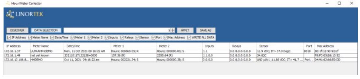
The easiest way to find your server’s IP address is by using the Linortek Hour Collector app. Once you open the HourCollector App, it will display all iTrixx devices that you have installed on the same network. If you can’t find the IP address, press the RESET button with a paper clip and it will identify upon reboot.
You may also find your device’s IP address by signing on to your router and searching the list of connected devices. Your iTrixx hour meter will be identified on your router as WiFiHM_xxxxxx where the x’s are the last 6 characters of the device’s MAC address. The Hour Collector app will display the following information:
PROGRAM ITRIXX FROM TELNET
You will need to use a Telnet client to configure your iTrixx server. To configure Telnet on Windows 8.1 or Windows 10, follow these steps:
- Open Control Panel
- Select Programs
- Under Programs and Features select Turn Windows features on or off
- Scroll down and select the checkbox for Telnet Client and click OK
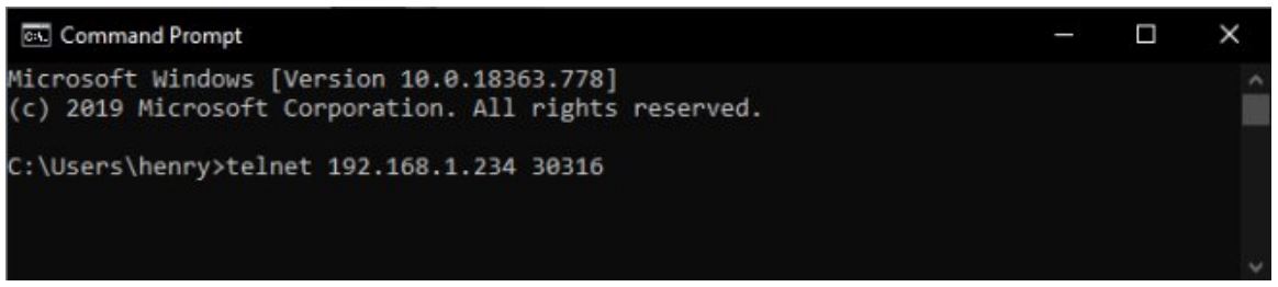
To connect to the iTrixx server using your PC, follow these steps:
- Search Command Prompt on your search bar (Windows 10), click and open Command Prompt
- Enter telnet nnn.nnn.nnn.nnn 30316 where n is your device’s IP address
- Once connected, it will prompt you for a password. By default, this password is the last 6 characters of its MAC address – without colons and all lower case– which can be found printed on the enclosure. (ex: cd56ef)
- After entering your password, all available commands will be listed in the command prompt window. For details of how to use the commands, please refer to Appendix 1: Available Commands.
You can also download a TCP Telnet app for a mobile device to be able to send Telnet commands to the WFMN from the mobile device as long as they are connected to the same WiFi network (does not work on cellular network).
AVAILABLE COMMANDS
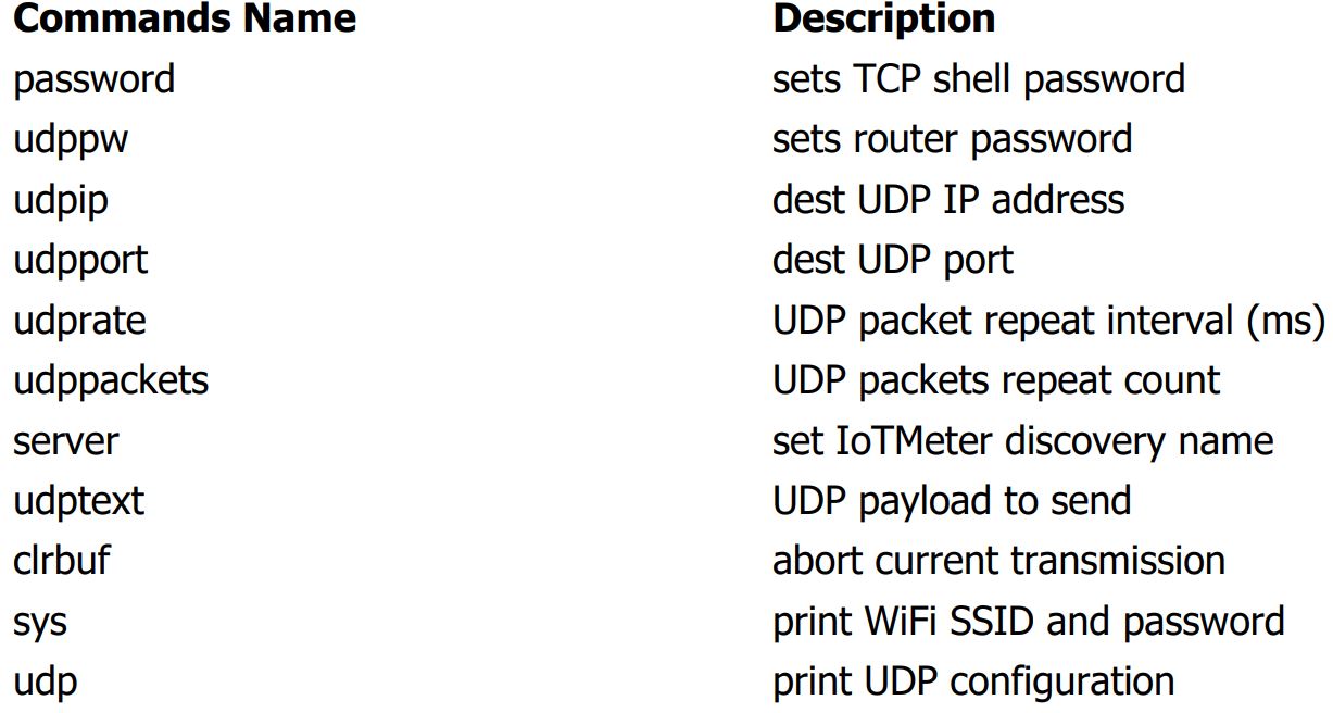
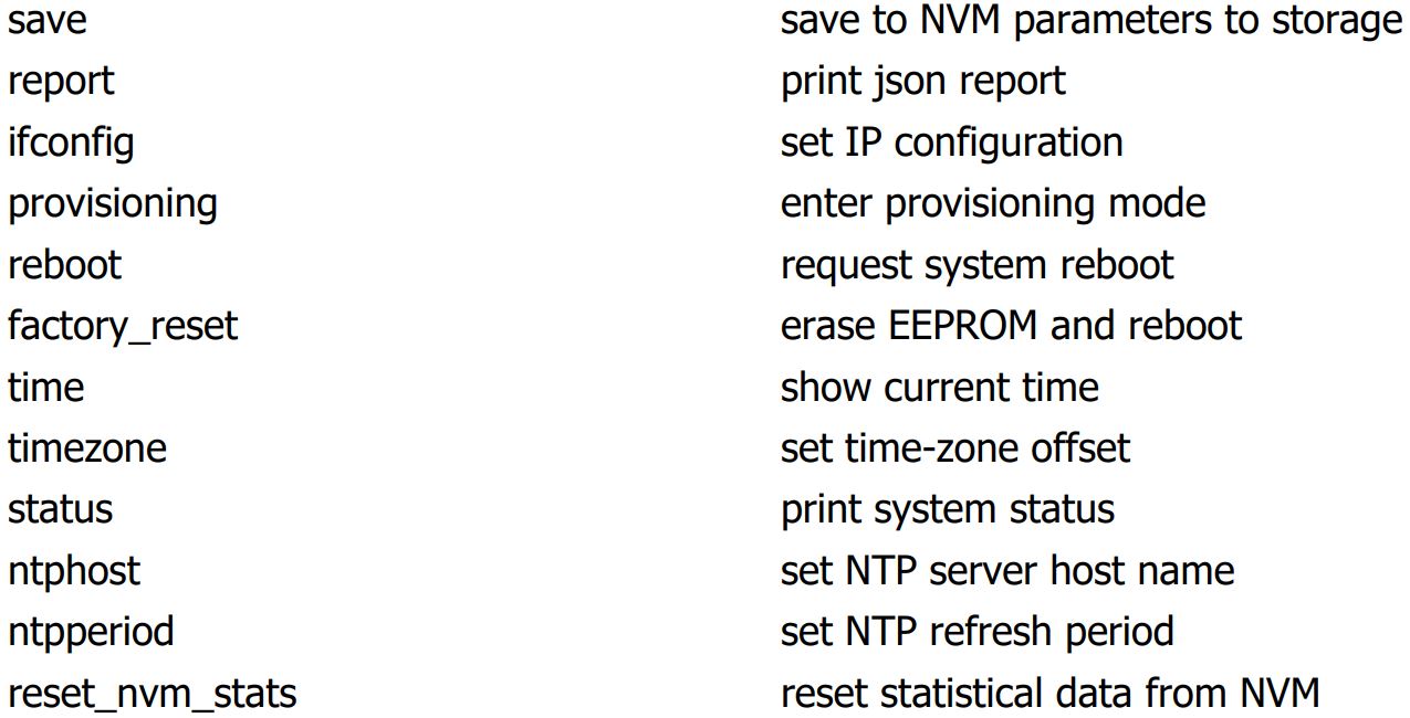
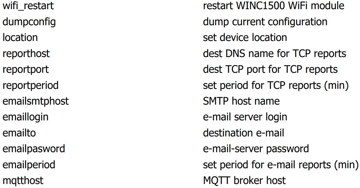
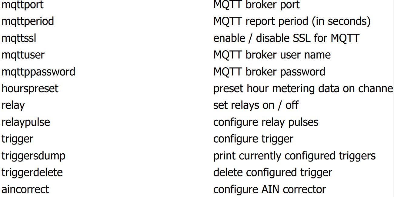
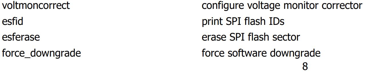
ITRIXX SERVER BASIC CONFIGURATION
To configure your server, you will need to issue commands via the Telnet terminal. This section will cover the basic configuration of your device. For a full list of commands and syntax, see the following pages.
IMPORTANT NOTE: Make certain to use the save command after making changes otherwise your changes will be lost when your server reboots.
- Naming your server
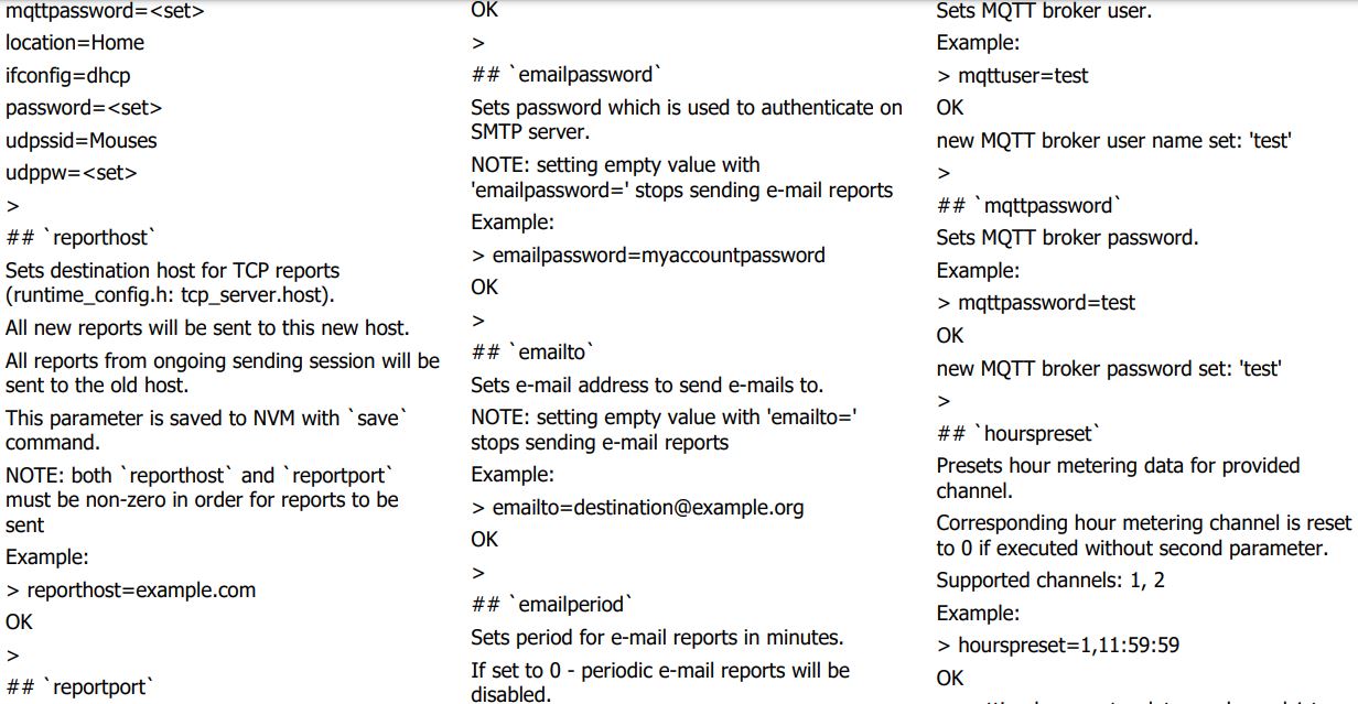
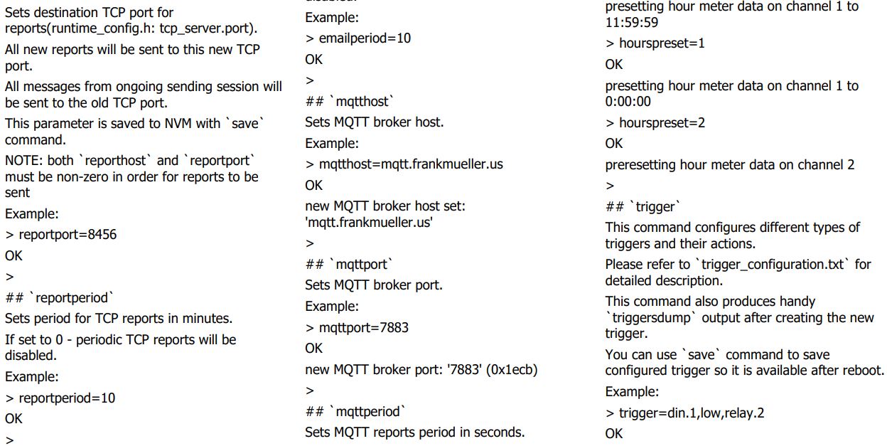
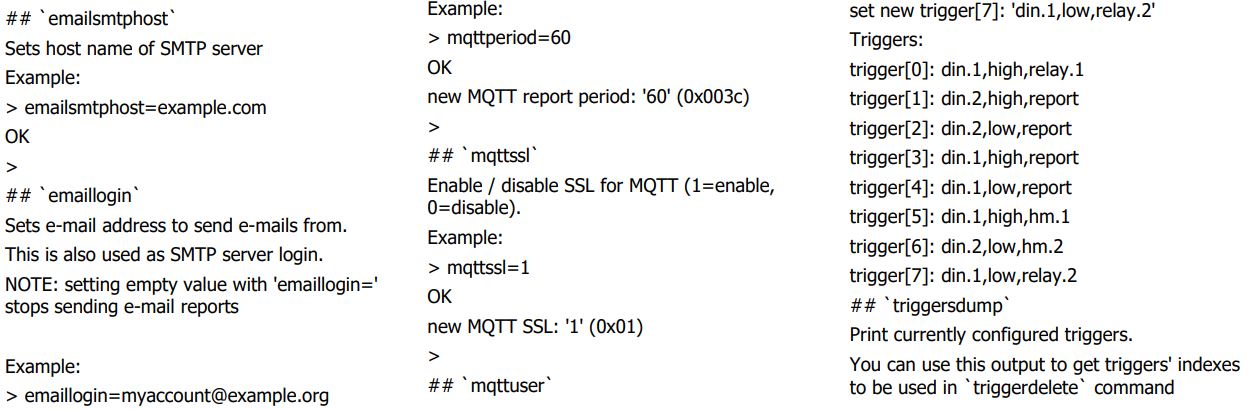
To make your iTrixx server more identifiable on your network, enter server= replacing with your desired server name. - Setting Time and Date
By default, your server is configured for GMT. To adjust the time zone, enter timezone=x where x is your time zone offset. For example: timezone=5 for EST, timezone=4 for EDT if you are in Eastern DayLight Saving time. To check your server’s time, you may enter the command: time. This will display the current time and date formatted as: yyyymmddThhmmss followed by the time zone offset (ISO 8601). For example: 20200422T1330000400 for 4/22/2020 1:30pm GMT4.
You may also set your preferred NTP server and update interval. By default, you server uses the NTP server: time.nist.gov and updates the time every 11 minutes. To change the NTP server, enter ntphost=<NTP host name> (ex: ntphost=time.nist.gov). To change the update frequency, use the command ntpperiod=x where x is the update frequency in minutes (ex: ntpperiod=11)
Note: If you build a dedicated network for the iTrixx to collect machine data without internet connection, the iTrixx server will not be able to reach the NTP server and update its time. To make the iTrixx server to get the time from your computer, you need to disable the NTP host with this command:
ntphost=
Once you click the Discover button on the HourCollector desktop app, it will send UDP message with current date/time to the iTrixx server. (This feature is available for software version 0.58.0v. and up) - IP Configuration
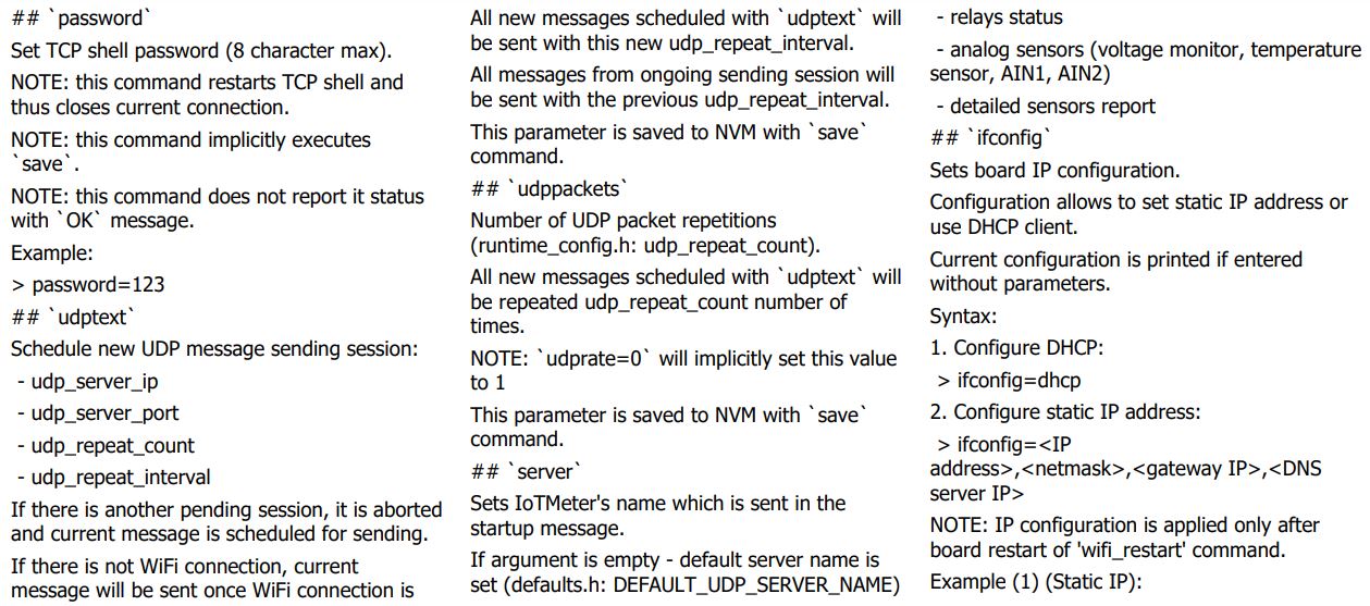
Once your SERVER is powered on and connected to the network, it will automatically obtain an IP address via DHCP as long as your router is configured to do so. If you wish to use a static IP address, you can use ifconfig command for IP configuration.
Configure static IP address:
> ifconfig=<IP address>,<netmask>,<gatway IP>,<DNS server IP>
NOTE: IP configuration is applied only after board restart of ‘wifi_restart‘ command. Example (1) (Static IP): > ifconfig=192.168.0.202,255.255.255.0,192.168.0.1,8.8.8.8 OK
Static IP configuration:
IP: 192.168.0.202 netmask: 255.255.255.0 default gateway: 192.168.0.1 DNS server: 8.8.8.8 >
To use DHCP: > ifconfig=dhcp - Enabling Email Notifications
The iTrixx server supports SSL. To enable email notifications, you will need your email provider’s SMTP server name, an email address to send from, the password for the account to send from, and an email address to send to. Use the following commands to configure your email:
>emailsmtphost= <SMTP>
• This command will set the SMTP server for the ‘send from’ email account o Ex: emailsmtphost=smtp.gmail.com
o SMTP servers include (but not limited to:
smtp.gmail.com (Gmail)
smtp.mail.yahoo.com (Yahoo Mail)
smtp.mail.me.com (iCloud)
>emaillogin=<email from>
• This command sets the username for the ‘send from’ email account
o Ex: emaillogin=myemail@gmail.com >emailpassword=
>emailpassword=<password>
• This command sets the password to the ‘send from’ email account
o Ex: emailpassword=mypassword
>emailto=<destination address>
• This command sets the ‘send to’ email account
o Ex: emailto=destination@yahoo.com You may set a periodic email report using the command: emailperiod=x where x is the interval in minutes to send an email report (ex: emailperiod=30 for a report every 30 minutes).
SETUP TRIGGERS
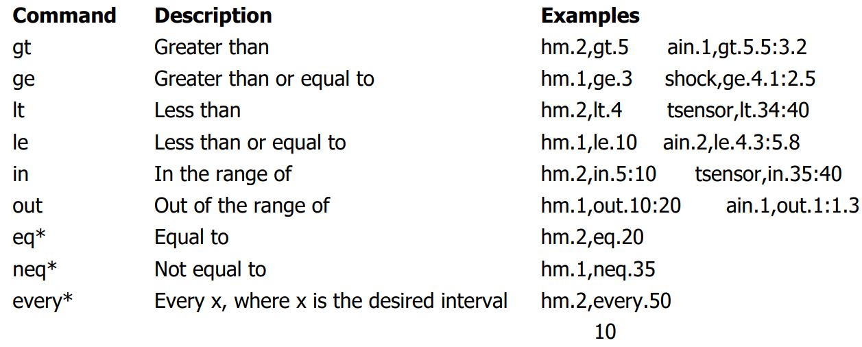
After configuring your iTrixx server, you can configure triggers to activate the different features of your device. Trigger syntax consists of 3 variables: a source (what activates the trigger), a value (the required condition of the source), and the target (what to do). Continue reading for a description of each variable. Each variable is separated by a comma.
The Trigger command configures different types of triggers and their actions. This command also produces handy `triggersdump` output after creating the new trigger. You can use `save` command to save configured trigger so it is available after reboot. Please refer to Appendix 2: Trigger Configuration for detailed description.
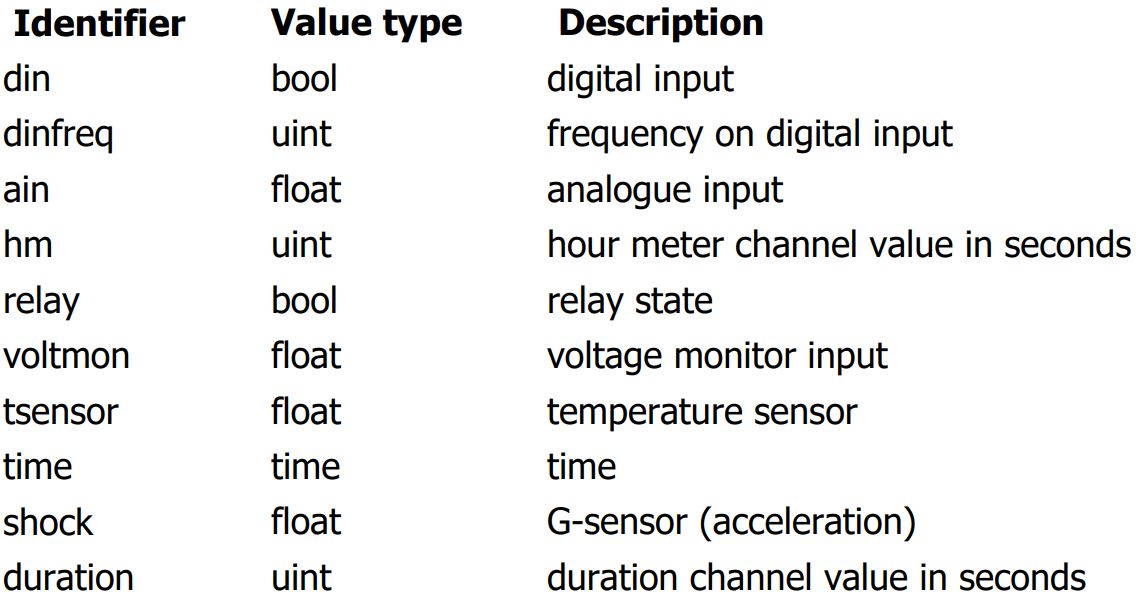
- Sources: Sources are what activates the trigger. The sources are:
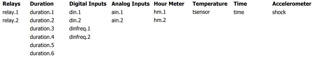
Notes on sources:
• The tsensor source uses the thermistor on the server’s circuit board. This temperature will be higher than ambient temperature and will be in Celsius (˚C).
• If using the time source to turn on a relay, the relay must have a duration configured.
• The shock source uses a value of 0.000 – 8.000. A value of 1 represents no movement. Higher values require increasing amounts of vibration or impact to activate the trigger.
• The duration measures time when `source` becomes active to the point when it gets inactive with 1 second accuracy. It is reset to zero when `source` becomes inactive and is never saved to nonvolatile memory thus it is *never* restored uponbootup. There are 6 `duration` channels in the device which can act either as trigger’s `target` or trigger’s `source`. - Values: The values you may use depends on which source you are using.
Relays and digital inputs may use a value of High or Low. For values for the analog inputs, hour meters, temperature, and accelerometer sources, see the table above. Analog inputs, digital frequency, temperature, and accelerometer values require 2 numbers separated with a colon. The first number is what is used to activate the trigger and the second number resets the trigger so it may activate again.
The time source can be set activate at a specified interval, or to activate on a specific time and date. The time value consists of 2 parts – a ‘repeat period’ and a ‘start date/time’. You do not need to use both parts. The ‘start date/time’ must be preceded by a colon, whether or not there is a ‘repeat period’ before it. See the following examples below.
• To activate relay 1 every 30 minutes, use the command: trigger=time,00.30,relay.1
• To activate relay 2 every hour, use the command: trigger=time,01.00,relay.2
• To send a report every 1.5 hours starting from 8th Apr 2020, 6:00pm, use the command:
trigger=time,01.30:20200408T1800,report
• To activate relay.1 at 4th July 2020, 12am, use the command: trigger=time,:20200704T0000,relay.1
* Can only be used for hour meter triggers
- Targets: The target is what is activated by the trigger.
The Target may be relay.1, relay.2, hm.1, hm.2, or report. The report target force updates the Hour Collector app and sends an email notification if configured.
See below for example triggers.
• trigger=relay.2,high,hm.2 (When relay 2 is on, iTrixx starts counting hour meter 2)
• trigger=din.1,high,hm.1 (When digital input 1 is on, iTrixx starts counting hour meter 1)
• trigger=voltmon,ge.3:0,hm.1 (When input voltage greater/equal to 3v, iTrixx starts counting hour meter 1)
• trigger=ain.2,lt.3.5:4.1,relay.2 (When analog input 2 value less than 3.5, turn relay 2 on, when value is higher than 4.1 reset the trigger)
• trigger=hm.1,eq.100,report (When hour meter 1 is equal to 100, send report)
• trigger=tsensor,ge.40:35,relay.1 (When temperature is greater/equal to 40, turn relay 1 on, when temperature is below 35, the trigger is reset)
• trigger=shock,gt.5:1,report (When accelerometer value is greater than 5, send report, when accelerometer is below 1, the trigger is reset)
To get a report when digital input 1 is staying on for more than 5 minutes you need to set two triggers:
• trigger=din.1,high,duration.1 (When digital input 1 is on, iTrixx starts counting duration 1)
• trigger=duration.1,ge.300,report (When duration 1 is greater/equal to 5 minutes, send report)
To view existing triggers, use the command triggersdump. This command will list all configured triggers in a numbered list. To delete a trigger, use the command triggerdelete=x where x corresponds to the number listed from the triggersdump command.
For more details of trigger configuration, please see Appendix 2: Trigger Configuration.
DATA MONITORING
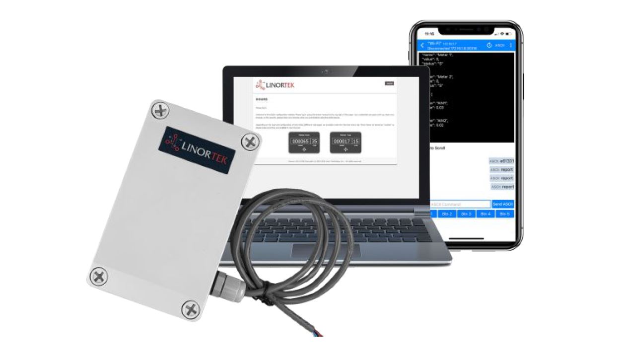
Once your iTrixx is wired and configured, it will periodically report its data over your network. You can use any computer to monitor the data using the HourCollector app, DataCollector app, or publish the hour readings as MQTT message and monitor the data remotely from your CMMS or other custom database as long as they subscribe to the topic on your broker.
MONITOR DATA ON LOCAL NETWORK
The HourCollector app was developed for use with iTrixx hour meter for free. For details of how to download and use this app, please refer to Connect to Your Network section of this manual.
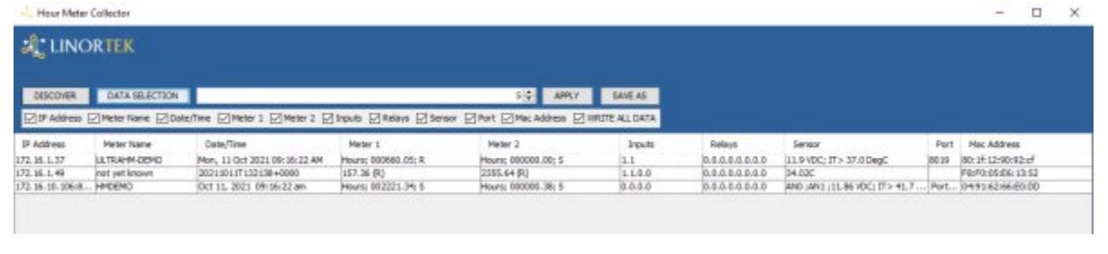
When first opening the HourMeter Collector app, it will display all Linortek Hour Meter devices as long as they are on the same subnet with the PC which you install the app.
DISCOVER: The App updates the data every 2 minutes automatically by default. If you want to manually refresh the data, you can click the DISCOVER button.
DATA SELECTION: The app will display the device IP Address, Meter Name, Date/Time, Meter 1, Meter 2, Inputs, Relays, Sensor, Port, Mac Address by default. If you only want to save some of the data, you can click the DATA SELECTION button, check/uncheck the boxes. If the box is not checked, the data won’t be saved on the CSV file. The “Write All Data” checkbox means it will write all the data to the .csv file, whether it is displayed or not displayed, unchecking this and then checking other data boxes will only write the selected data to the .csv file.
DATA COLLECTION FREQUENCY: You can change the frequency in minutes up to 1440 minutes on the frequency bar on the app. Please note: the number you put on the frequency bar must be in MINUTES! After entering the number, click Apply.
SAVE AS: The HourMeter Collector App can save all the data to a CSV file once you open it. When you use the app the first time, it will create a folder on the desktop named CSV_FILE. Inside is a .csv file containing a log the data collected by the hour collector app, this file can be viewed using MS Excel. If you delete the file, it will create a new one at the same location next time when you open the app.
If you want to change the file location, click the SAVE AS button, it will open a new window, give the file a name, select the file location. In order for this log to update, the HourMeter Collector app must be running and the .csv file must NOT be open otherwise the HourCollector app cannot automatically edit the file.
Note: If you change a new file location, the old file data won’t be copied to the new location.
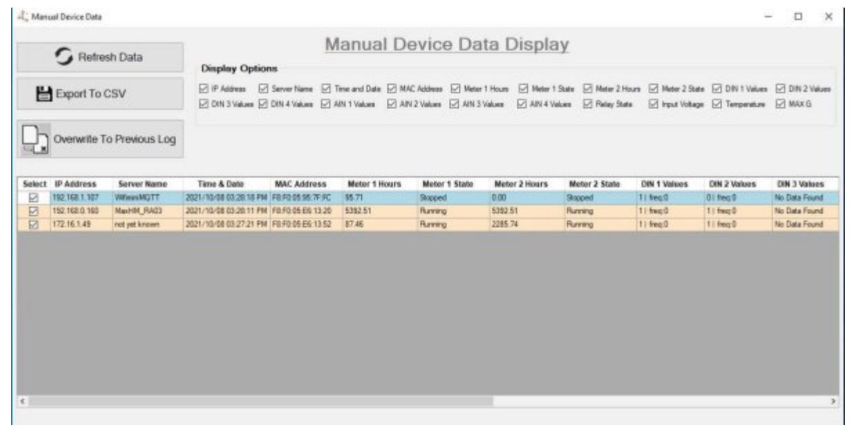
On the app, it will display the following information:
- IP Address: The IP address of your iTrixx device. If you have ported the device to the Internet, the port number will display after the IP address.
- Meter Name: The meter’s name, it displays as “not yet known” for the iTrixxWFMN and “SERVER” for iTrixxNHM by default if you haven’t changed it.
- Date/Time: Current date and time.
- Meter 1: Current hour readings. R:the meter is running, S: the meter has stopped.
- Meter 2: Current hour readings. R:the meter is running, S: the meter has stopped.
- Input: Input 1 and input 2 status, 1 means the input is on, 0 is off.
- Relay: Relay status, 1 means the relay is on, 0 is off.
- Sensor: It displays the voltage and temperature information on the board.
- Portr: If the device is ported, the port number will display.
- MAC Address: The MAC address of the board.
MONITOR DATA REMOTELY
With the builtin MQTT protocol, you can have the iTrixx server to send (publish) MQTT message to a Gateway (brocker), use an MQTT client such as MQTTSPY, CMMS or our free DataCollector desktop app on remote PC and subscribe to the broker to receive data. To use the MQTT protocol, an MQTT Gateway will be needed (sold separately), if you have multiple iTrixx devices from different locations, all of the iTrixx units can send data to the gateway as long as it’s ported to the Internet. We will use the DataCollector desktop app to demostrate how to monitor the data remotely.
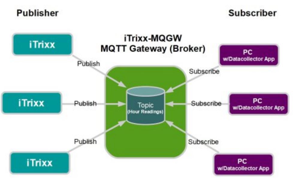
- Install the gateway on your network, configure the broker
For instructions of how to install the gateway and configure the broker, please refer to iTrixx MQTT Gateway and WFMN Bundle Setting Instruction, which can be downloaded from https://www.linortek.com/downloads/documentations/. If you use your own gateway (broker), please refer to the instruction of your brocker provider as to how to install and configure. In order for remote accessing the data, you will need to port the gateway to the Internet. For instruction of how to port the gateway to the Internet, please refer to the video tutorial on our website Technical Support page: https://www.linortek.com/technicalsupport/, or consult your IT professional. - Connect iTrixx to publish data to the Broker
After setting up your broker, you will need to configure the iTrixx to connect to the broker through Telnet. Login to your device on Telnet, type in the following commands:
>mqtthost=98.25.185.186
>mqttport=1883
>save
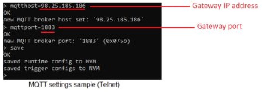 The iTrixx will now publish its payload at a 1minute interval.
 - Install the DataCollector Pro App
The DataCollector Pro app is an upgraded version of the HourCollector app. Like our HourCollector App, this app can listen for UDP broadcasts from our hour meter devices. It can record and log this data into a .csv file. It can not only display the hour readings and digital/analog input data for each meter, allow you to select manually/automatically collecting/exporting data, but also can be used to monitor the data remotely. The DataCollector Pro App can be downloaded here:
https://www.linortek.com/downloads/supportprogramming/.
Alternatively, you can also set it to manually acquire data. This is useful for port forwarded network hour meters as it can go out to the internet and read data off the device’s XML pages. It can also collect data from the iTrixx WiFi Hour Meter both via REST or subscribe to an MQTT broker.- Install the DataCollector
1). Run ndp48web.exe (this will install .net framework if it is not already on your computer)
2). Run SQLServer2016SSEIExpr.exe (this will install SQL server)
a. Choose custom install, follow the prompts until you are given a checklist of features to install. make sure to check “LocalDB” at the bottom of the list.
b. All other options can be left as default
3). Copy the linortek_db folder to your C: drive
4). Run LinorTekSetup.msi to install the program.
5). If your PC has already installed previous version, you have to uninstall previous version “Linortek Data Collector App” from Control panel>> Add remove program and then new version “Linortek Data Collector.msi” setup file need to install. - Configure the DataCollector
App Settings
Open the Data Collector app and navigate to the App Settings window.
a. Set desired date and time format
b. Choose whether you wish for data collector to listen for UDP message from Linortek devices (easy) or to manually collect device data (advanced)
c. Choose whether to log data
d. Choose update frequency
Connect the App to the Broker
a. Click Add Device button
b.Connection Type: Select MQTT WiFi Hourmeter from the dropdown list
c. Device Name: Give a name for the broker
d. Address/Web URL: Enter the broker IP address
e. Port Number: Enter the broker port number if ported
f. MQTT Topic: Enter lt1000/+/tele
Once you click save, click the Data Display tab on the app, you will see all devices connected to that broker. Please note: When monitoring the data from DataCollector App remotely, you can only view the data from manual mode.
- Export the Data
If using Automatic mode, open the Data Display window. Data will be shown as it is received.
a. Click on Export to CSV if you want to export just real time data log
b. Click on Export Automatic Device Data Log if you want to download all previous data logs
Note: if the log is not exported periodically, the amount of system memory required to export will increase and may cause the app to not respond. If this happens, delete the device data log.
- Install the DataCollector
DATA INTEGRATION
There are several ways to integrate the data collected by the iTrixx: JSON, UDP, MQTT. MQTT are very commonly used by many of our customers.
With the MQTT protocol builtin, it provides a standard method of communication for iTrixx to reliably communicate data across networks with any IoT platform and applications. If you are interested in using the MQTT, please refer to the iTrixx WFMN MQTT – Product Documentation.
For more information, documentation and howto videos, visit https://www.linortek.com/technicalsupport/ or look us up on our YouTube page.
CONTACT SUPPORT TEAM
If you need assistance on setting your devices, please feel free to contact us:
Phone: (001)3364856199
Email: support@linortek.com
You can also start a chat from our website to reach our support teams.
Winston Salem, NC 27127
info@linortek.com
Information subject to change without notice www.linortek.com
0150800010B
1021 R003V003
Printed in U.S.A.
Appendix 1: Available Commands
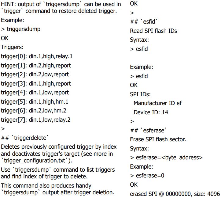
You can use `save` command to save configuration with deleted trigger so it is not restored after reboot.
Example:
> triggerdelete=6
OK
Triggers:
trigger[0]: din.1,high,relay.1
trigger[1]: din.2,high,report
trigger[2]: din.2,low,report
trigger[3]: din.1,high,report
trigger[4]: din.1,low,report
trigger[5]: din.1,high,hm.1
trigger[7]: din.1,low,relay.2
>
## `aincorrect`
Configure AIN corrector.
Vcorr = V * multiplier + offset
If offset is not provided, it will be set to 0.00.
Syntax:
>
aincorrect=<channel>,<multiplier>[,<offset>]
channel 1 or 2
Example:
> aincorrect=1,1.05,2.00
OK
> ## `voltmoncorrect`
Configure voltage monitor corrector.
Vcorr = V * multiplier + offset
If offset is not provided, it will be set to 0.00.
Syntax:
> voltmoncorrect=<multiplier>[,<offset>]
Example:
> voltmoncorrect=1.05,2.00
Appendix 2: Trigger Configuration
# Triggers configuration (v0.58.0)
This document describes how to configure triggers with `trigger`, `triggerclear` and `triggersdump` commands. Trigger is a configuration object which consists of *source*, *condition*, and *target*, where *source* is the source of event, *condition* is a condition against which *source’s* input is tested, and *target* is an action which is taken when *condition* becomes active (true). For example, *high* signal level on a DIN *source* input can be configured to *trigger* relay state: trigger=din.1,high,relay.1
## `trigger` command
This command allows to configure certain input events to trigger certain actions. It accepts 3 parameters (descriptors) separated with comas: trigger=<source>,<condition>,<target>
If command’s parameter is correct, an unconfigured trigger is taken from the pool and configured appropriately.
There are 20 trigger descriptors available to be configured (buffer_sizes.h: TRIGGERS_NUMBER_MAX).
If all trigger descriptors are configured, the command will fail.
All configured triggers can be persistently saved with `save` command.
### *source* descriptor
Source descriptor consists of source identifier and optional channel number which are separated with period.
Channel numbering starts from 1.
Every source can be assigned to a number of targets.
F.e. `din.1` can be configured to trigger relay action, hourmeter action, and report. The following table describes *source* identifiers:
Examples:
* `din.1` -digital input, channel 1
* `ain.2` -analogue input, channel 2
* `hm.1` -hour meter, channel 1
* `tsensor` -temperature sensor
* `shock` -absolute acceleration in G (range 0..8 G)
* `duration.4` -duration, channel 4
**NOTE**: source identifier influences value type for condition.
### *condition* description
Conditions are tested against *source* input value and when it becomes true, *target* is activated.
When condition becomes false, *target* is deactivated.
There are different *condition* descriptors for different *source* value types.
#### bool conditions
For *bool* type sources, bool condition format must be used. `<bool_active_value>` (see table above) can take 2 values: `high`, or `low`.
Example: set up a trigger, which will activate `relay.1` when `din.1` becomes `high`: trigger=din.1,high,relay.1
Example: set up a trigger, which will activate `relay.2` when `din.1` becomes `low`: trigger=din.1,low,relay.2
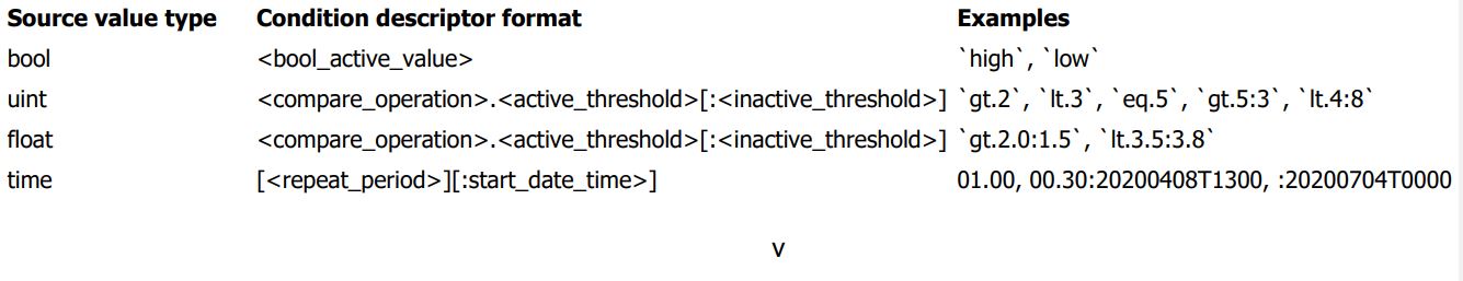
#### *uint* and *float* conditions
For *uint* and *float* type sources the following condition format must be used:<compare_operation>.<active_threshold>[:<inactive_threshold>]
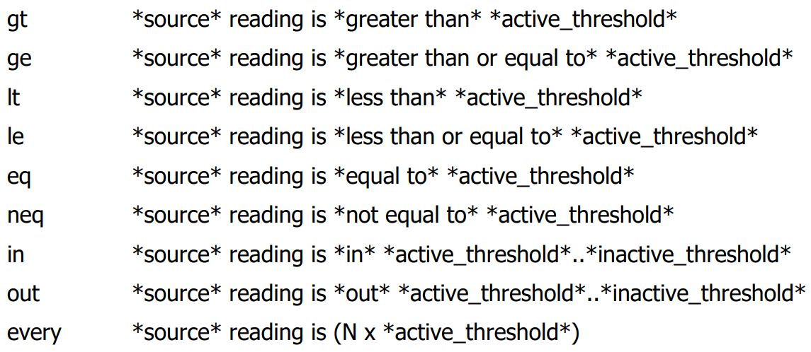
Where *compare_operation* is the operation which will be performed on *source* value. It can be one of:
`gt` greater than
`ge` greater than or equal
`lt` less than
`le` less that of equal
`eq` equal
`neq` not equal
`in` in range
`out` out of range
`every` true when *source* value reaches (N x *active_threshold* where N is unsigned integer.
**NOTE**: use of `eq` and `neq` for *float* types is not allowed due to *float* type inaccuracy.
**NOTE**: `every` condition is active for a very short period of time which is enough to trigger report sending but is not enough for relay targets. If used with relay targets, relay pulse must be configured appropriately.
Once *compare_operation* on *source* reading and *active_threshold* becomes `true`, the *target* gets activated.
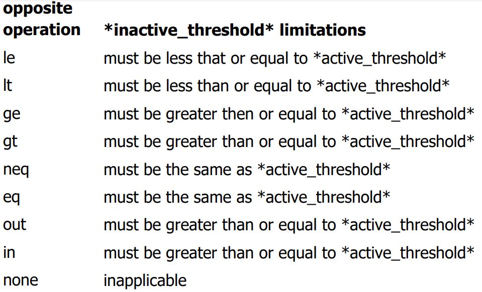
Deactivation rule is built implicitly by applying operation which is *the opposite* to the provided one. Refer to the table below to get a reference on opposite compare operations.
Once *opposite compare_operation* on *source* reading and *inactive_threshold* becomes `true`, the *target* gets deactivated.
*inactive_threshold*, if not provided explicitly, gets assigned to the *active_threshold* value.
Providing *inactive_threshold* explicitly allows to set up a hysteresis for *source* value readings.
**NOTE**: `eq`, `neq` and `every` operation does not allow to provide *inactive_threshold* and it is always implicitly set to the same value as *active_threshold*.
Example: configure a trigger which sends *report* when *hour meter 1* reading becomes greater than *3600* seconds:
trigger=hm.1,gt.3600,report
Example: configure a trigger which activates *relay 1* when *AIN 1* reading becomes greater than *2.2* and deactivates it when *AIN 1* reading becomes less that or equal to *1.5*:
trigger=ain.1,gt.2.2:1.5,relay.1
Example: configure a trigger which activates *relay 1* every 3 hours (10800 seconds) measured by hour meter:
trigger=hm.1,every.10800,relay.1
Operation Description
#### *time* conditions
*time* condition consists of optional *repeat_period* and optional *start_date_time*. *repeat_period* specifies trigger activation period. This is an optional part and *time* trigger will fire just once if *repeat_period* is omitted.
*repeat_period* has 1 minute precision and must be in the following format:
<HH>.<MM>
Where `HH` stands for hours (0023), `MM` minutes (0059).
*start_date_time* defines absolute time at which condition will start to be applied. This is an optional part and is set to current time if omitted.
*start_date_time* has 1 minute precision and is assumed to be in local time zone (GMT offset is taken into account). It must be in the following format:
<YYYYmmddTHHMM>
Where `YYYY` stands for year, `mm` for month (0112), `dd` day of month (from 01 to 28, or 29, or 30, or 31), `HH` hours (0023), `MM` minutes (0059)
Timezone is optional and is set to the current timezone if omitted.
NOTE: *start_date_time* is specified in current local time while is saved in UTC time and will not be automatically modified if you change timezone with `timezone` command.
I.e. if you had timiezone configured as ‘7’ (timezone=7), then configured a timetrigger ‘trigger=time,:20200601T1200,relay.1’ which is supposed to fire.
at 12:00 current local time (05:00 UTC), and then changed the timezone to ‘2’, the trigger will still fire a 05:00 UTC which is 03:00 new local time. Example: make `report` every hour starting from now:
trigger=time,01.00,report
Example: make `report` every 30 minutes starting from now: trigger=time,00.30,report
Example: make `report` every 1.5 hours starting from 8th Apr 2020, 18:00 (local time): time,01.30:20200408T1800,report
Example: activate `relay.1` at 4th July 2020, 00:00 local time: time,:20200704T0000,relay.1
### *target* descriptor
Target descriptor consists of target identifier and optional channel number which are separated with period.
Channel numbering starts from 1.
It has the same format as source descriptor and differ on by available identifiers.
**NOTE**: Most targets can have just *one* source, i.e. if a target is configured to act upon certain source input,
attempt to include the same target into a different trigger will fail.
The following table describes *target* identifiers:
Identifier Description
relay relay channe
hm hour meter channel
report send reports
duration duration channel
Example: set up a trigger which will send reports when `din.1` becomes `high`
trigger=din.1,high,report
Example: set up another trigger which will send reports when `din.2` becomes `low`
trigger=din.2,low,report
## **`hm`** channels
**`hm`** stands for hour meter.
Each `hm` channel represents an accumulative meter which measures *total time* of `source` being active with 1 second accuracy.
It is not reset when `source` becomes inactive and can only be reset by a special command.
`hm` value is saved to nonvolatile memory across reboot or power down and is restored upon bootup.
There are 2 `hm` channels in the device which can act either as trigger’s `target` or trigger’s `source`.
## **`duration`** channels
**`duration`** measures time from the point when `source` becomes active to the point when it gets inactive with 1 second accuracy.
It is reset to zero when `source` becomes inactive and is never saved to nonvolatile memory thus it is *never* restored upon boot up.
There are 6 `duration` channels in the device which can act either as trigger’s `target` or trigger’s `source`.