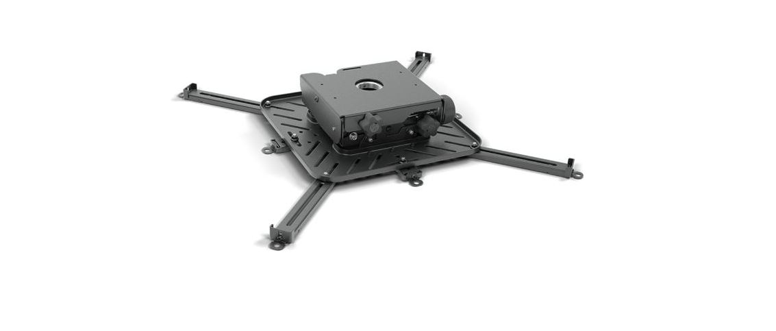
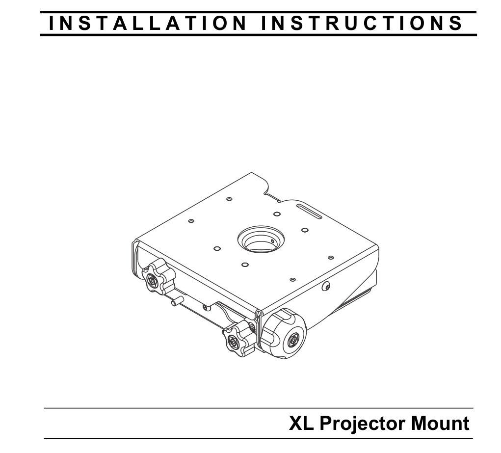
Instruction Manual of CHIEF VCT
XL Projector Mount
DISCLAIMER
Legrand | AV and its affiliated corporations and subsidiaries (collectively “Legrand | AV”), intend to make this manual accurate and complete. However, Legrand | AV makes no claim that the information contained herein covers all details, conditions or variations, nor does it provide for every possible contingency in connection with the installation or use of this product. The information contained in this document is subject to change without notice or obligation of any kind. Legrand | AV makes no representation of warranty, expressed or implied, regarding the information contained herein. Legrand | AV assumes no responsibility for accuracy, completeness or sufficiency of the information contained in this document.
Chief® is a registered trademark of Legrand AV Inc.
DEFINITIONS
MOUNTING SYSTEM: A MOUNTING SYSTEM is the primary Chief product to which an accessory and/or component is attached.
ACCESSORY: AN ACCESSORY is the secondary Chief product which is attached to a primary Chief product, and may have a component attached or setting on it.
COMPONENT: A COMPONENT is an audiovisual item designed to be attached or resting on an accessory or mounting system such as a video camera, CPU, screen, display, projector, etc.
![]()
WARNING: A WARNING alerts you to the possibility of serious injury or death if you do not follow the instructions.
![]()
CAUTION: A CAUTION alerts you to the possibility of damage or destruction of equipment if you do not follow the corresponding instructions.
 IMPORTANT SAFETY INSTRUCTIONS
![]()
WARNING: Failure to read, thoroughly understand, and follow all instructions can result in serious personal injury, damage to equipment, or voiding of factory warranty! It is the installer’s responsibility to make sure all mounting systems are properly assembled and installed using the instructions provided.
![]()
WARNING: Failure to provide adequate structural strength for this mounting system can result in serious personal injury or damage to equipment! It is the installer’s responsibility to make sure the structure to which this mounting system is attached can support five times the combined weight of all equipment. Reinforce the structure as required before installing the mounting system.
![]()
WARNING: Exceeding the weight capacity can result in serious personal injury or damage to equipment! It is the installer’s responsibility to make sure the combined weight of all components located between the supporting structure and the VCT does not exceed 150 lbs (68.0 kg).
- The weight capacity of the VCT may be LIMITED to the lowest weight capacity of any other component located between the VCT and the supporting structure.
![]()
WARNING: Use this mounting system only for its intended use as described in these instructions. Do not use attachments not recommended by the manufacturer.
![]()
WARNING: Never operate this mounting system if it is damaged. Return the mounting system to a service center for examination and repair.
![]()
WARNING: Do not use this mounting system outdoors.
IMPORTANT ! : The VCT mounting system is designed to be mounted to:
- a 1-1/2″ NPT or NPSM following ANSI/ASME B1.20.1 (Schedule 40, 0.154″ minimum thickness steel or aluminum-ASTM B221) threaded extension column (not included).
–SAVE THESE INSTRUCTIONS–
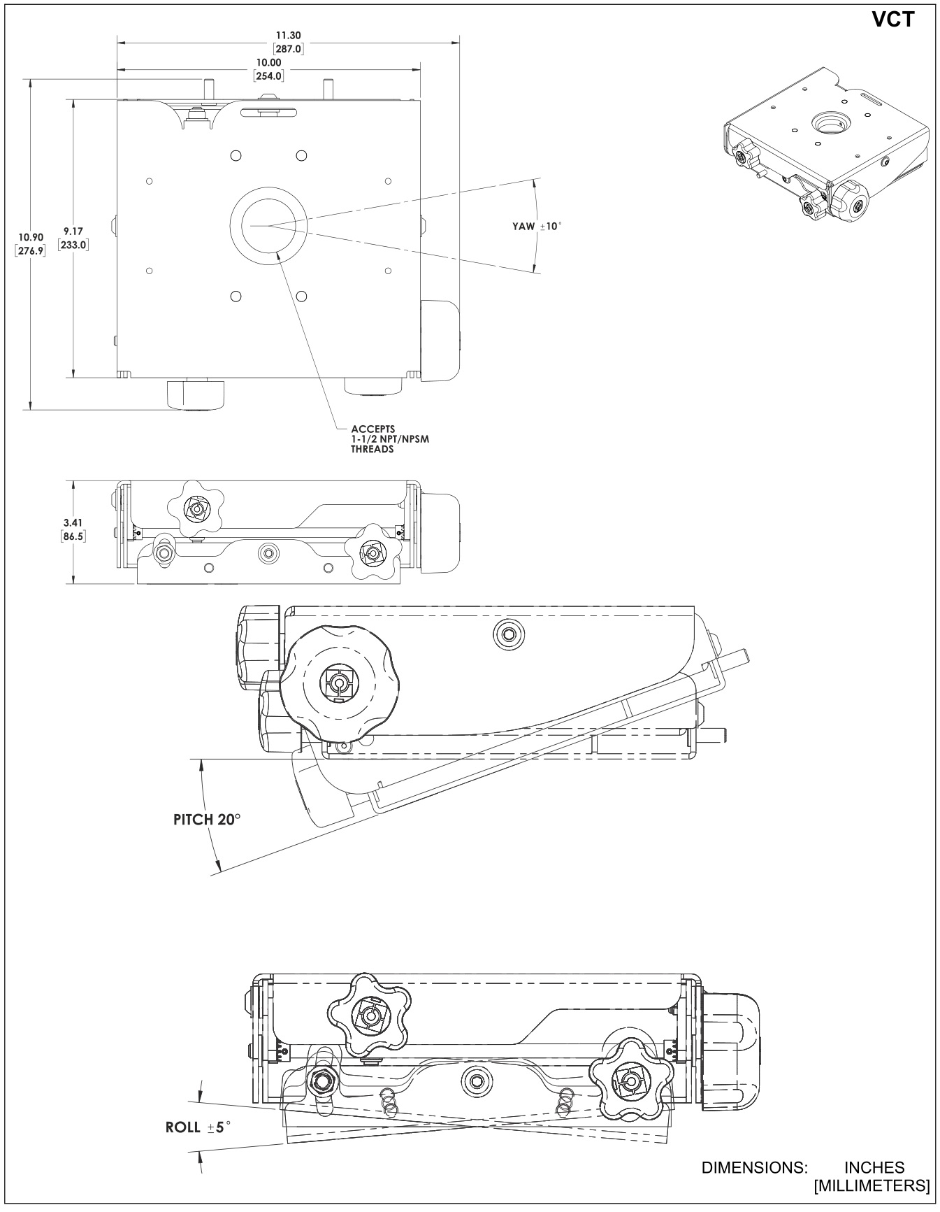
DIMENSIONS
LEGEND
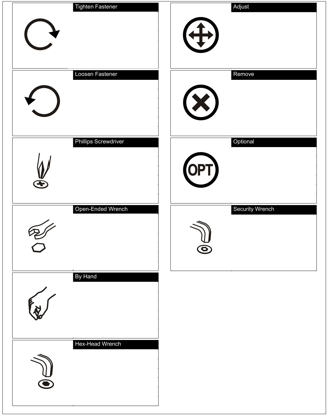
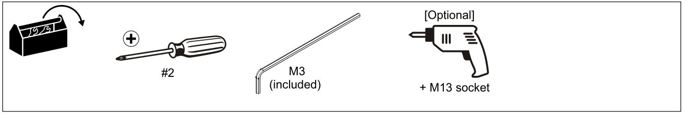
TOOLS REQUIRED FOR INSTALLATION
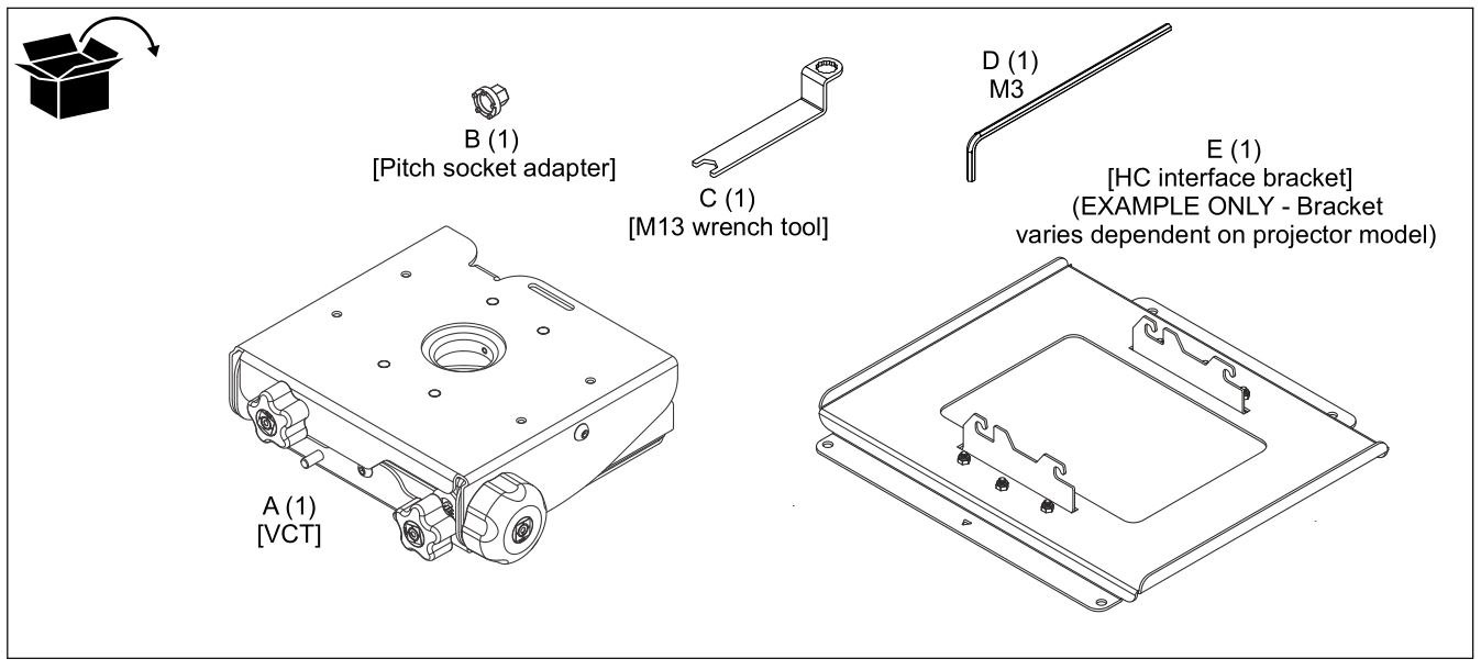
PARTS
INSTALLATION
NOTE: In the following instructions, the term VCT refers to the VCTXXXX.
The VCT mount is designed to be mounted to:
- a 1-1/2″ NPT or NPSM following ANSI/ASME B1.20.1 (Schedule 40, 0.154″ minimum thickness steel or aluminum-ASTM B221) threaded extension column (not included).
Installing VCT to Extension Column
IMPORTANT ! : These installation instructions assume that a 1-1/2″ NPT or NPSM (Schedule 40, 0.154″ minimum thickness steel or aluminum – ASTM B221) pipe (not included) has been properly installed and is in place.
- Loosen and remove the set screw which ships installed in the VCT mount (A). (See Figure 1)
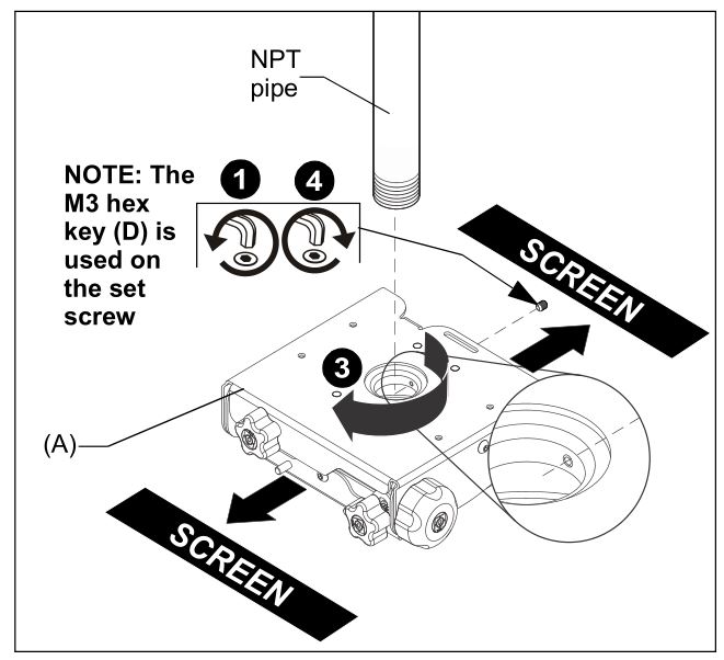
Figure 1
2. Loosely add four M8 flange nuts (included with interface bracket) on two PEM studs at each end of the VCT mount (A). (See Figure 2)
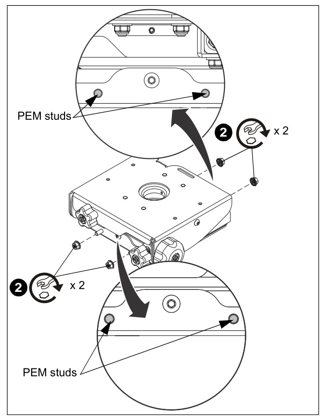
Figure 2
3. Thread the VCT mount (A) onto the existing 1-1/2″ NPT pipe until tight with a minimum of four threads engaged. (See Figure 1)
NOTE: Ensure that side of VCT mount with two knobs is located parallel to, or opposite of, the screen. (See Figure 1)
4. Tighten the set screw into the VCT mount threaded collar to prevent movement of the VCT. (See Figure 1)
INSTALLING PROJECTOR
IMPORTANT ! : Model VCT uses Chief “HC” Series interface brackets. (See Parts drawing).
Installing Interface Bracket
![]()
WARNING: IMPROPER INSTALLATION CAN LEAD TO PROJECTOR FALLING RESULTING IN SERIOUS PERSONAL INJURY OR DAMAGE TO EQUIPMENT. DO NOT substitute hardware. Use only the hardware provided by the manufacturer.
1. Secure HC interface bracket to projector using installation instructions and hardware provided with HC interface bracket.
Install Projector with Attached Interface Bracket
1. Orient projector with attached interface bracket so that it is square to the screen. (See Figure 3)
2. Lift the projector and install it behind the flange nuts on the four studs extending from the VCT housing. (See Figure 3)
![]()
WARNING: IMPROPER INSTALLATION CAN LEAD TO PROJECTOR FALLING RESULTING IN SERIOUS PERSONAL INJURY OR DAMAGE TO EQUIPMENT! Ensure that the interface bracket hooks are seated on studs on VCT mount!
3. Tighten the flange nuts on the four studs. (See Figure 3)
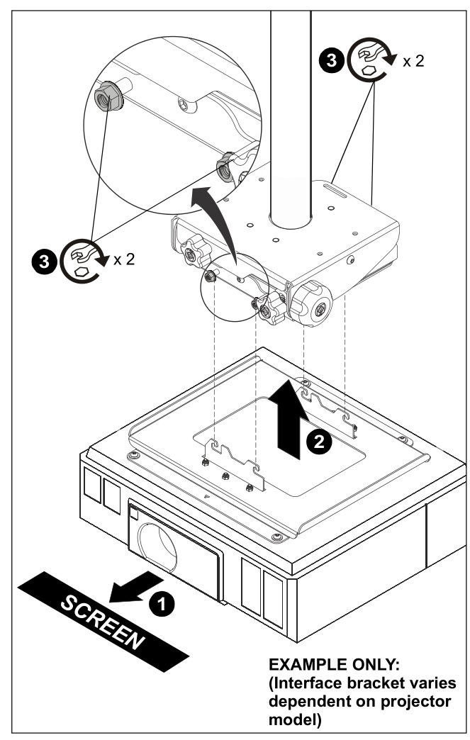
Figure 3
Adjustments
![]()
WARNING: MOUNTING HARDWARE IS TO BE LOOSENED ONLY ENOUGH TO ALLOW FOR NECESSARY MOVEMENT. Over-loosening or removal of mounting hardware may result in personal injury or serious damage to equipment!
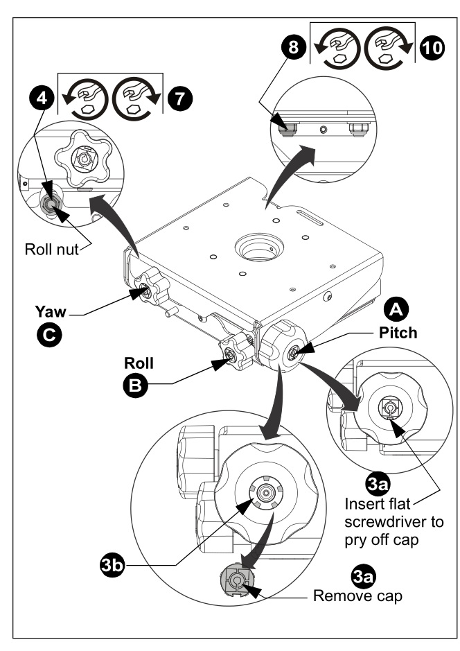
Figure 4
A. Pitch
- Turn PITCH knob (A) counterclockwise to pitch down. (See Figure 4)
- Turn PITCH knob (A) clockwise to pitch up to 0°.
- If adjusting for a large degree of pitch:
• 3a: Pry off center cap from PITCH knob by inserting screwdriver into slot
• 3b: Insert pitch socket adapter (B) into knob
• 3c: Adjust pitch socket adapter by hand, or use a drill with an M13 socket to adjust PITCH to desired level.
• 3d: Remove pitch socket adapter from knob and replace knob center cap.
B. Roll
4. Loosen Roll nut (located immediately below and left of YAW knob [black nut on white mount, silver on black mount]). (See Figure 4)
5. Turn ROLL knob clockwise to move side of mount near knob down.
6. Turn ROLL knob counterclockwise to move other side of mount down.
7. Tighten Roll nut (located immediately below and left of YAW knob).
C. Yaw
8. Loosen Yaw nut (black nut on white mount, silver on black mount) accessible through back of mount. (See Figure 4)
9. Adjust YAW by rotating mount around column as required.
10. Tighten Yaw nut.
![]()
8800-003322 Rev00
©2021 Legrand | AV
www.legrandav.com
08/2021
USA/International
A 6436 City West Parkway, Eden Prairie, MN 55344
P 800.582.6480 / 952.225.6000
F 877.894.6918 / 952.894.6918
Europe
A Franklinstraat 14, 6003 DK Weert, Netherlands
P +31 (0) 495 580 852
F +31 (0) 495 580 845
Asia Pacific
A Office No. 918 on 9/F, Shatin Galleria 18-24 Shan Mei Street Fotan, Shatin, Hong Kong
P 852 2145 4099
F 852 2145 4477
![]()