EMERSON Rosemount 1067 Temperature Sensor Guide
1 About this guide
This guide provides basic guidelines for Rosemount 1067 Sensor models. It does not provide instructions for configuration, diagnostics, maintenance, service, troubleshooting, explosion-proof, flameproof, or intrinsically safe (I.S.) installations.
If the Rosemount 1067 Sensor was ordered assembled to a temperature transmitter, see the appropriate transmitter Quick Start Guide for information on configuration and hazardous locations certifications.
NOTICE
Complications can arise when sensors and the transmitters to which they are assembled are certified to compatible, but have unique approvals. Be aware of the following situation:
- If an I.S. approved Rosemount 1067 Sensor is ordered with a housing, a transmitter enclosed in that housing may have a different I.S. approval rating. Refer to the transmitter IS certificate if applicable.
- If a sensor and transmitter have different certifications, or if either has more certifications than the other, installation must comply with the most restrictive requirements of either component. This is especially (but not exclusively) relevant when combination approvals are ordered on either the sensor or transmitter. Review certifications on both the sensor and transmitter for installation requirements and ensure installation of the sensor/transmitter assembly complies with a single certification that is shared by both of these components and that meets the requirements of the application.
⚠ WARNING
Explosions could result in death or serious injury.
Installation of this sensor in an explosive environment must be in accordance with the appropriate local, national, and international standards, codes, and practices. Conduit/cable entries
- Unless marked, the conduit/cable entries in the transmitter housing use a 1/214 NPT thread form. Entries marked “M20” are M20 1.5 thread form. On devices with multiple conduit entries, all conduit entries will have the same thread form.
- When installing in a hazardous location, use only appropriately listed or Ex certified flameproof/dust plugs, adapters, or glands in cable/conduit entries.
- Only use plugs, adapters, glands, or conduit with a compatible thread form when closing these entries.
Physical Access
- Unauthorized personnel may potentially cause significant damage to and/or misconfiguration of end users’ equipment. This could be intentional or unintentional and needs to be protected against.
- Physical security is an important part of any security program and fundamental to protecting your system. Restrict physical access by unauthorized personnel to protect end users’ assets. This is true for all systems used within the facility.
⚠ CAUTION
Refer to Product Certification section of this Quick Start Guide documentation.
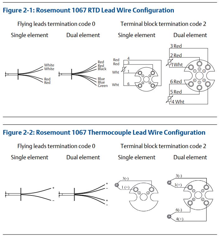
2 Wiring diagrams
3 Dimensional drawings
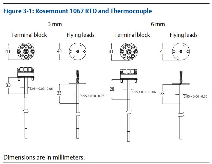
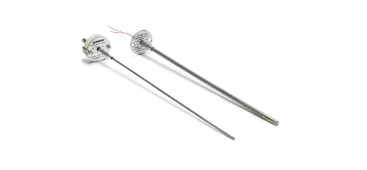
3.1 Sensor assembly
Figure 3-2: Sensor Assembly
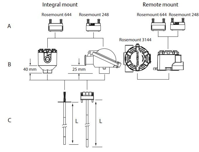
- A. Head or field mount transmitters
- B. Connection heads
- C. Sensor with flying leads, terminal block
Note Sensor assemblies can be provided without an enclosure or with an enclosure such as the connection heads shown above or assembled to a Rosemount transmitter.
4 Specifications
4.1 Material selection
Emerson provides a variety of Rosemount product with various product options and configurations including materials of construction that can be expected to perform well in a wide range of applications. The Rosemount product information presented is intended as a guide for the purchaser to make an appropriate selection for the application. It is the purchaser’s sole responsibility to make a careful analysis of all process parameters (such as all chemical components, temperature, pressure, flow rate, abrasives, contaminants, etc.), when specifying product, materials, options and components for the particular application. Emerson is not in a position to evaluate or guarantee the compatibility of the process fluid or other process parameters with the product, options, configuration or materials of construction selected.
4.2 Rosemount 1067 Platinum RTD
100 RTD at 0 °C, = 0.00385 / × °C
Temperature range 196 to 300 °C (320.8 to 572 °F)
Insulation resistance
1,000 M minimum insulation resistance when measured at 500 Vdc and at room temperature.
Sheath material 316 SST/321 SST with mineral-insulated cable construction
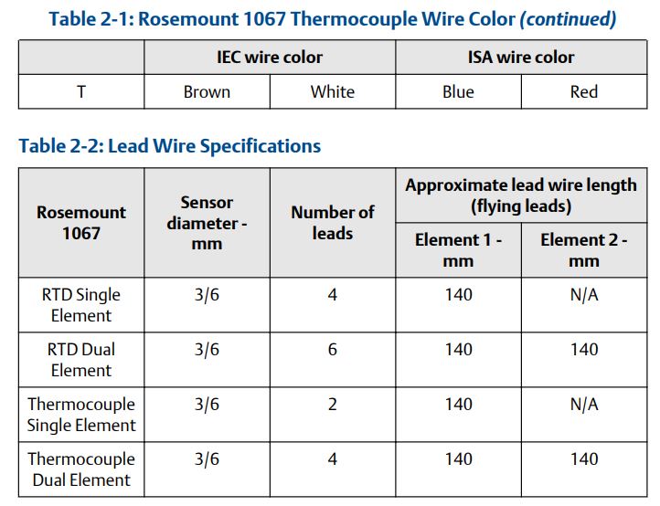
Lead wire
PTFE insulated, 24 AWG, silver-plated copper wire. See Figure 2-1 for wire configuration.
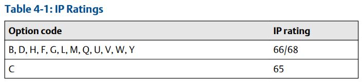
Ingress Protection (IP) ratings
Thermal response time
Thermal response times for the 1067 sensor only. Tested in accordance to IEC 751 guidelines.
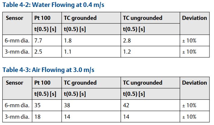
More response time information is available online for other sensor and thermowell configurations
4.3 Rosemount 1067 Thermocouple
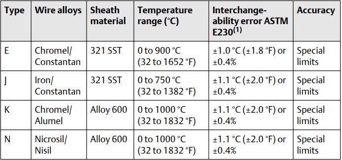
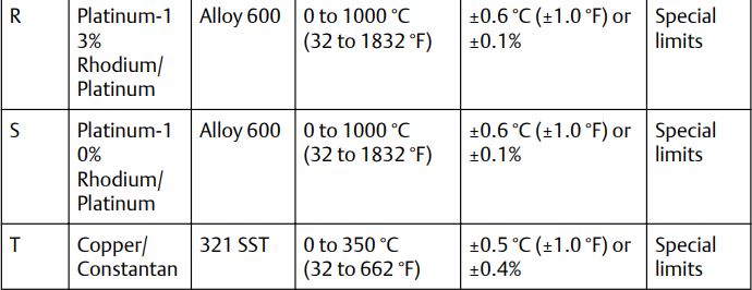
Temperature range
See Table 4-4 and Table 4-5.
Insulation resistance
1,000 M minimum insulation resistance when measured at 500 Vdc and at room temperature.
Sheath material
Rosemount thermocouples are made of a mineral insulated cable design wit h a variety of sheath materials available to suit both the temperature and the environment. For temperature up to 800 °C (1472 °F) in air, the sheath is made from 321 SST. For temperatures above 800 °C (1472 °F) in air, the sheath is made from Alloy 600. For strongly oxidizing or reducing atmospheres, consult your local Emerson representative for information.
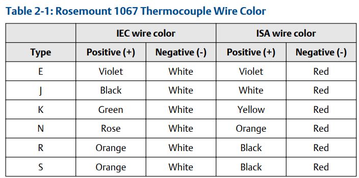
Lead wires
Thermocouple, internal 19 AWG solid wire (max) and 21 AWG solid wire (min.). External extension leads, Type E, J, K, N, R, S, and T. PTFE insulated. 20 AWG (max.) and 24 AWG (min.) Color coded per IEC or ISA standards. Figure 2-2 shows the wire configuration.
Ingress Protection (IP) ratings
For information see Table 4-1.
Table 4-4: Characteristics of 1067 IEC Thermocouples (IEC Standards are Typically Used in European Applications)
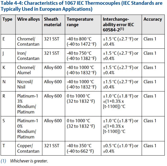
Table 4-5: Characteristics of 1067 ASTM Thermocouples (ASTM Standards are Typically Used in North American Applications) (continued)
4.4 Functional specifications
Power Overvoltage category I
Environmental Pollution degree 4
Emerson.com/Rosemount
5 Product certifications
Rev 2.4
5.1 European Directive Information
A copy of the EU Declaration of Conformity can be found at the end of the Quick Start Guide. The most recent revision of the EU Declaration of Conformity can be found at Emerson.com/Rosemount.
5.2 Ordinary Location Certification
As standard, the transmitter has been examined and tested to determine that the design meets the basic electrical, mechanical, and fire protection requirements by a nationally recognized test laboratory (NRTL) as accredited by the Federal Occupational Safety and Health Administration (OSHA).
5.3 North America
The US National Electrical Code® (NEC) and the Canadian Electrical Code (CEC) permit the use of Division marked equipment in Zones and Zone marked equipment in Divisions. The markings must be suitable for the area classification, gas, and temperature class. This information is clearly defined in the respective codes.
5.3.1 USA
E5 US Explosion proof, Dust-Ignition proof
Certificate FM17US0170X
Standards FM Class 3600: 2011; FM Class 3611: 2004; FM Class 3615: 2006; FM Class 3810: 2005; ANSI/NEMA® – 250: 1991
Markings XP CL I, Div 1, GP B, C, D; DIP CL II/III, Div 1, GP E, F, G; T5(50 °C Ta 85 °C); when installed per Rosemount drawing 00068-0013; Type 4X
5.3.2 Canada
E6 Canada Explosion proof and Dust-Ignition proof
Certificate 70044744
Standards CAN/CSA C22.2 No. 0:2010, CAN/CSA No. 25-1966 (R2000), CAN/CSA C22.2 No. 30-M1986 (R2012), CAN/CSA C22.2 No. 94-M1991 (R2011), CAN/CSA C22.2 No. 61010-1:2012
Markings XP CL I, DIV 1, GP B, C, D; DIP CL II, DIV 1, GP E, F, G; CL III; T6 (50 °C Ta +80 °C), T5 (50 °C Ta +95 °C); Seal not required; installed per Rosemount drawing 00068-0033; Type 4X and IP 66/67; Vmax 35 VDC, 750 mWmax
5.4 Europe
5.4.1 E1 ATEX Flameproof
Certificate FM12ATEX0065X
Standards EN 60079-0: 2012+A11:2013, EN 60079-1: 2014, EN 60529:1991 +A1:2000+A2:2013
Markings II 2 G Ex db IIC T6…T1 Gb; T6…T1: Ta = 50 °C to + 40 °C; T5…T1: Ta= 50 °C to +60 °C See Process temperature limits for process temperatures.
Special Conditions for Safe Use (X):
- See certificate for ambient temperature range.
- The non-metallic label may store an electrostatic charge and become a source of ignition in Group III environments
- Guard the LCD display cover against impact energies greater than 4 joules.
- Flameproof joints are not intended for repair.
- A suitable certified Ex d or Ex tb enclosure is required to be connected to temperature probes with Enclosure option “N”.
- Care shall be taken by the end user to ensure that the external surface temperature on the equipment and the neck of DIN Style Sensor probe does not exceed 130 °C.
- Non-Standard Paint options may cause risk from electrostatic discharge. Avoid installations that cause electrostatic build-up on painted surfaces, and only clean the painted surfaces with a damp cloth. If paint is ordered through a special option code, contact the manufacturer for more information.
5.4.2 ND ATEX Dust
Certificate: FM12ATEX0065X
Standards: EN 60079-0: 2012+A11:2013, EN 60079-31:2014, EN 60529:1991 +A1:2000+A2:2013
Markings: II 2 D Ex tb IIIC T130 °C Db Ta= 40 °C to +70 °C; IP66 See Process temperature limits for process temperatures.
Special Conditions for Safe Use (X):
- See certificate for ambient temperature range.
- The non-metallic label may store an electrostatic charge and become a source of ignition in Group III environments.
- Guard the LCD display cover against impact energies greater than 4 joules.
- Flameproof joints are not intended for repair.
- A suitable certified Ex db or Ex tb enclosure is required to be connected to temperature probes with Enclosure option “N”.
- Care shall be taken by the end user to ensure that the external surface temperature on the equipment and the neck of DIN Style Sensor probe does not exceed 130 °C.
- Non-Standard Paint options may cause risk from electrostatic discharge. Avoid installations that cause electrostatic build-up on painted surfaces, and only clean the painted surfaces with a damp cloth. If paint is ordered through a special option code, contact the manufacturer for more information.
5.4.3 I1 ATEX Intrinsic Safety
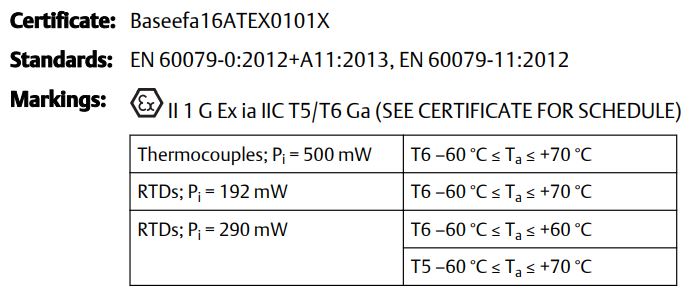
Special Conditions for Safe Use (X): The equipment must be installed in an enclosure which affords it a degree of ingress protection of at least IP20.
5.5 International
5.5.1 E7 IECEx Flameproof
Certificate: IECEx FMG 12.0022X
Standards: IEC 60079-0:2011, IEC 60079-1:2014
Markings: Ex db IIC T6…T1 Gb; T6…T1: Ta= 50 °C to +40 °C; T5…T1: Ta= 50 °C to +60 °C See Process temperature limits for process temperatures.
Special Conditions for Safe Use (X):
- See certificate for ambient temperature range.
- The non-metallic label may store an electrostatic charge and become a source of ignition in Group III environments.
- Guard the LCD display cover against impact energies greater than 4 joules.
- Flameproof joints are not intended for repair.
- A suitable certified Ex d or Ex tb enclosure is required to be connected to temperature probes with Enclosure option “N”.
- Care shall be taken by the end user to ensure that the external surface temperature on the equipment and the neck of DIN Style Sensor probe does not exceed 130 °C.
- Non-Standard Paint options may cause risk from electrostatic discharge. Avoid installations that cause electrostatic build-up on painted surfaces, and only clean the painted surfaces with a damp cloth. If paint is ordered through a special option code, contact the manufacturer for more information.
5.5.2 NK IECEx Dust-Ignitionproof
Certificate: IECEx FMG 12.0022X
Standards: IEC 60079-0:2011, IEC 60079-1:2013 Markings: Ex tb IIIC T130 °C Db Ta= 40 °C to +70 °C; IP66
See Process temperature limits for process temperatures.
Special Conditions for Safe Use (X):
- See certificate for ambient temperature range.
- The non-metallic label may store an electrostatic charge and become a source of ignition in Group III environments
- Guard the LCD display cover against impact energies greater than 4 joules.
- Flameproof joints are not intended for repair.
- A suitable certified Ex db or Ex tb enclosure is required to be connected to temperature probes with Enclosure option “N”.
- Care shall be taken by the end user to ensure that the external surface temperature on the equipment and the neck of DIN Style Sensor probe does not exceed 130 °C.
- Non-Standard Paint options may cause risk from electrostatic discharge. Avoid installations that cause electrostatic build-up on painted surfaces, and only clean the painted surfaces with a damp cloth. If paint is ordered through a special option code, contact the manufacturer for more information.
5.5.3 I7 IECEx Intrinsic Safety
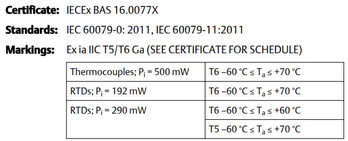
Special Conditions for Safe Use (X): The equipment must be installed in an enclosure which affords it a degree of ingress protection of at least IP20
5.5.4 E2 Brazil Flameproof and Dust-Ignitionproof
Certificate: UL-BR 13.0535X
Standards: ABNT NBR IEC 60079-0:2013, ABNT NBR IEC 60079-1:2016, ABNT NBR IEC 60079-31:2014
Markings: Ex db IIC T6…T1 Gb; T6…T1: Ta= 50 °C to +40 °C; T5…T1: Ta= 50 °C to +60 °C; Ex tb IIIC T130 °C Db IP66; (40 °C Ta +70 °C)
Special Conditions for Safe Use (X):
- See product description for ambient temperature limits and process temperature limits.
- The non-metallic label may store an electrostatic charge and become a source of ignition in Group III environments.
- Guard the LCD display cover against impact energies greater than 4 joules.
- Consult the manufacturer if dimensional information on the flameproof joints is necessary.
- A suitable certified Ex “d” or Ex “tb” enclosure is required to be connected to temperature sensors with Enclosure option “N”.
- Care shall be taken by the end user to ensure that the external surface temperature on the equipment and the neck of DIN Style Sensor probe does not exceed 130 °C.
- For all equipment, non-standard paint options may cause risk from electrostatic discharge. Avoid installations that cause electrostatic build-up on painted surfaces, and only clean the painted surfaces with a damp cloth. If paint is ordered through a special option code, contact the manufacturer for more information.
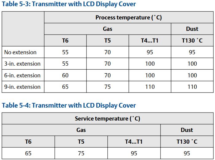
5.6 Process temperature limits
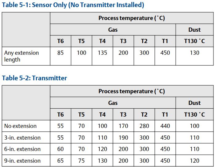
Adhering to the process temperature limitations of Table 5-3 will ensure that the service temperature limitations of the LCD display cover are not exceeded. Process temperatures may exceed the limits defined in Table 5-3 if the temperature of the LCD display cover is verified to not exceed the service temperatures in Table 5-4 and the process temperatures do not exceed the values specified in Table 5-2.
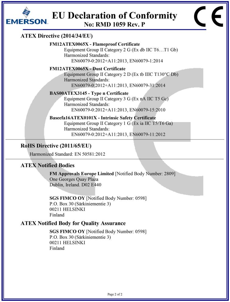
6 Declaration of Conformity
Figure 6-1: Rosemount 1067 Declaration of Conformity
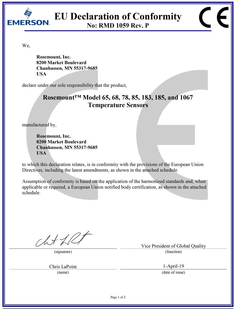
![]()
Quick Start Guide
00825-0100-4951, Rev. BC
March 2021
For more information: www.emerson.com
©2021 Emerson. All rights reserved. Emerson Terms and Conditions of Sale are available upon request. The Emerson logo is a trademark and service mark of Emerson Electric Co. Rosemount is a mark of one of the Emerson family of companies. All other marks are the property of their respective owners.![]()