
DYNOJET PC6-17053 Power Commander 6

Installation Guide
INPUT ACCESSORY GUIDE
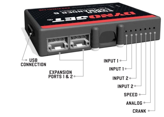
OPTIONAL ACCESSORY INPUTS
Map (Input 1 or 2) The PC6 has the ability to hold 2 different base maps. You can switch on the fl y between these two base maps when you hook up a switch to the MAP inputs. You can use any open/close type switch. The polarity of the wires is not important.
Shifter (Input 1 or 2) Used for clutch-less full throttle upshifts. Insert the wires from the Dynojet quick shifter into either Input 1 or Input 2. The polarity of the wires is not important. Set to Input 2 by default.
Speed If your application has a speed sensor then you can tap into the signal side of the sensor and run a wire into this input. This will allow you to calculate gear position in the Control Center Software. Once gear position is setup you can alter your map based on gear position and setup gear dependent kill times when using a quick shifter.
Analog This input is for a 0-5v signal such as engine temp, boost, etc. Once this input is established you can alter your fuel curve based on this input in the Power Core software.
Launch You can connect a wire to either Input 1 or Input 2 and then the other end to a switch. This switch when engaged (continuity) will only allow the RPM to be raised to a certain limit (set in the software). When released, you will have full RPM.
WIRE CONNECTIONS
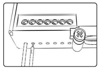
To input wires into the PC6 fi rst remove the rubber plug on the backside of the unit and loosen the screw for the corresponding input. Using a 22-24 gauge wire, strip about 10mm from its end. Push the wire into the hole of the PC6 until it stops and then tighten the screw. Make sure to reinstall the rubber plug.
NOTE: If you tin the wires with solder it will make inserting them easier.
INSTALLING THE POWER COMMANDER 6
- Remove the main seat and the passenger seat.
- Remove the fuel tank shroud.
- Unbolt and prop the front of the fuel tank.
- Remove the battery cover.
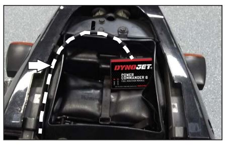
- Place the PC6 module in the tail section and route the harness forward towards the engine along the right hand side of the bike.
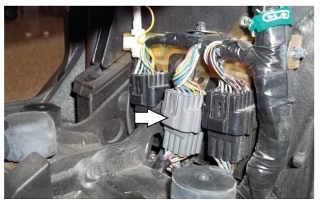
- Locate and unplug the stock sub-harness connector for the bike’s fuel injectors.
This is a GREY 16-pin connector located under the fuel tank just rear of the battery on the right side of the bike. - Plug the pair of BLACK 16-pin connectors from the PC6 wiring harness in-line of the stock GREY 16-pin connectors.
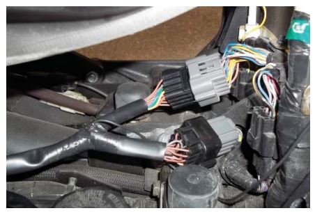
Try to keep the extra connectors as far down and forward as possible to keep from interfering with the fuel tank when it gets lowered. - Locate and unplug the WHITE 2-pin connectors.
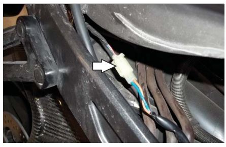
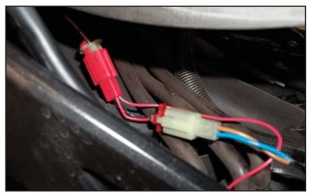
This pair of connectors is located beneath the fuel tank towards the rear of the bike. - Plug the pair of RED 2-pin connectors from the PC6 wiring harness in-line of the stock WHITE 2-pin connectors.
- Secure the PC6 ground wire with the small ring lug to the negative (-) terminal of the bike’s battery
- Using the supplied Velcro, secure the PC6 module inside of the tail section.
Clean both surfaces with the supplied alcohol swab prior to applying the Velcro adhesive. - Reinstall the fuel tank, seats, and body work.Download the latest map fi les from our web site at dynojet.com/tunes.
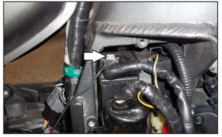
Optional Inputs:
Speed – YELLOW wire on larger ECU connector (pin #11). 12v Source for Autotune – RED wire from 3-pin tail lightconnector.

2191 MENDENHALL DRIVE, NORTH LAS VEGAS, NV 89081 – 800-992-4993 – DYNOJET.COM
© 2004-2022 DYNOJET RESEARCH ALL RIGHTS RESERVED