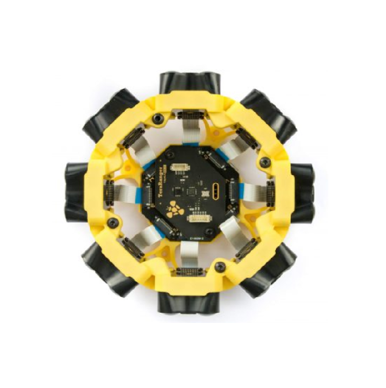
Terabee TeraRanger Multiflex Time-of-Flight sensor Installation Guide
Website: http://www.teraranger.com/
Technical support: support@teraranger.com
Commercial: teraranger@terabee.com
About the TeraRanger Multiflex
1. Inside the Package
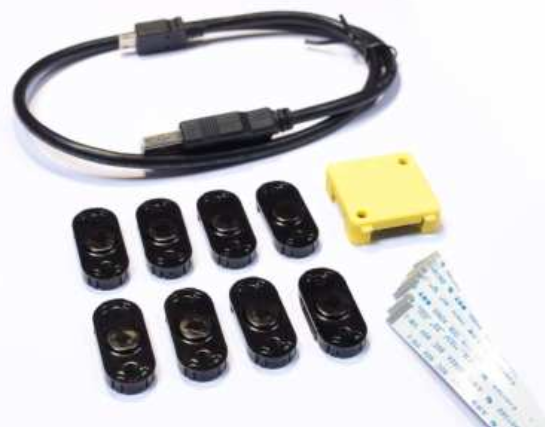
You will receive the following items when purchasing the TeraRanger Multiflex:
- 8 assembled sensors with covers
- Multiflex Hub with case
- 8 flat flex cables (10cm)
- Micro USB cable (50cm)
Upto 4 additional covers are included in the pack. If a sensor is not performing as expected, try using one of the spare covers as dirty, dusty or scratched covers can impede sensor performance.
2. Safety Note
Each TeraRanger Multiflex sensor contains a laser emitter and corresponding drive circuitry. The laser output power must not be increased by any means and no optics should be used with the intention of focusing the laser beam.
3. Dimensions and Mounting
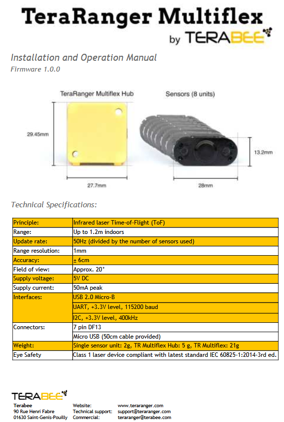
TeraRanger Multiflex sensors are enclosed with polycarbonate covers. For optimal performance please make sure that the covers are touching the sensor’s PCB by screwing the sensor units to a flat surface using M3 screws.
The TeraRanger Multiflex provides two mounting holes on both: (a) the TeraRanger Multiflex Hub (Figure 1), and (b) the sensor units (Figure 2). Both pairs of mounting holes are designed for M3 screws. The individual distances between the holes, and the sensor external dimensions are illustrated in the two figures below.
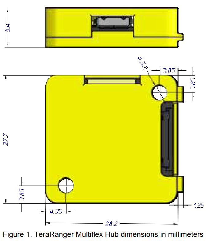
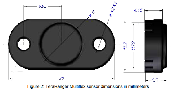
The following aspects should be taken into consideration when mounting the TeraRanger Multiflex:
- Do not remove the plastic covers as this will misalign the optics and degrade the sensor’s performance.
- Sensors should not be connected or disconnected from the strip while the Multiflex is powered.
- Do not mount the TeraRanger Multiflex Hub onto hot surfaces or near other sources of heat. If possible, allow the board to properly radiate its heat or mount it in a ventilated place.
- Take all usual precautions for sensitive electronics such as maintaining a suitable distance from strong electric and magnetic fields, strong radio emitters, etc.
- Maintain clean mounting environment (dust entering behind the lens can severely affect performance).
4. Details on Supply Voltage
TeraRanger Multiflex Hub works with a supply voltage of 5V +-0.25V. Please make sure that the supply voltage has low ripple and avoid strong inductive loads on the same supply to keep it free of voltage spikes and drops.
5. About the Connector
The TeraRanger Multiflex Hub connects to your equipment using a 7-pin connector from the Hirose DF13 series. (The part number of the corresponding female connector is DF13-7S-1.25C.) The TeraRanger Multiflex does not ship with a connector cable, but we recommend purchasing the female connector here. Please use Figure 3 and following table to identify the pins:
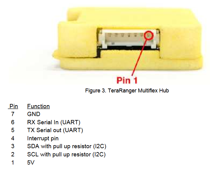
Important:
- Once connected, DF13 connectors are very reliable and are perfect for robotics and drone environments where vibrations are common. These connectors are not, however, designed for continuous plugging and unplugging. If you need to plug and unplug the sensors frequently, consider adding a more suitable connector in-line.
- Please do not apply shear forces to the connector when pushing it in the socket. Ideally, press the socket down to the PCB with your thumb and push the connector in with your other hand. Do not use tools like pliers etc!
- Please follow basic rules on ESD safety when connecting and touching the TeraRanger Multiflex or TeraRanger Multiflex Hub!
- Do not plug/unplug sensors from the TeraRanger Multiflex Hub while the device is powered. Always disconnect the power supply first!
6. UART Data Interface (default)
UART is available on pins 5 and 6. It accepts input voltage levels from 3.3V up to 5V. The output voltage level is 3.3V. Please use a serial to USB interface (e.g. FTDI breakout boards) to connect the TeraRanger Multiflex Hub to a computer via the UART interface.
Do not connect the TeraRanger Multiflex Hub to a real RS232 PC port, the voltage levels are different and this might destroy the board’s electronics.
The UART interface is configured to send and receive data at a transfer speed of 115200 bit/s with 8 data bits, no parity bit and one stop bit (115200-8N1). More information on the different operation modes can be found in Section 4 (Protocol Description) of this manual.
7. I2C Data Interface
Another way to connect to the TeraRanger Multiflex Hub is via I2C interface. Using this interface, you can connect a TeraRanger Multiflex sensor strip to an I2C master. In the current firmware version, the I2C base address is fixed to 0x55. Please consider that due to the fixed I2C base address, you can only run one TeraRanger Multiflex per I2C bus. Nevertheless, you can connect other devices with different base addresses to the same bus, but please make sure that the I2C master of the bus can still drive the sum of all pull-up resistors on the bus.
Please refer to Section 1.5 (About the Connector) for the electrical connections to be made for using I2C. The signal levels are 3.3V, the maximum bus speed is 400kHz and the pull-up resistors (1.5kOhms) are already integrated in the TeraRanger Multiflex Hub.
8. USB Interface
You can directly connect the TeraRanger Multiflex Hub to your computer using a micro USB cable. This cable will provide power and data communication. For both Linux and Mac operating systems, a driver for this interface is already installed and the interface will appear as a virtual COM port. It is configured to send and receive at 115200 bit/s with 8 data bits, no parity bit and one stop bit (115200-8N1). If you are using Windows, please download the driver from http://www.st.com/en/development-tools/stsw-stm32102.htmland carefully follow the ”ReadMe file” instructions given by the installer. After successful installation, unplug the interface for a moment and plug it back in. The virtual COM port should now be available on your PC.
Note: Do not plug and/or unplug the sensor units while the TeraRanger Multiflex is powered by a computer. Disconnect the USB cable first!
9. Normal Operation
Each time the TeraRanger Multiflex Hub is powered, the GREEN LED will turn on. At the same time, the Hub will detect how many sensors are connected. The ORANGE LED will blink once for each sensor detected. It can take a few seconds before the distance values become available on the UART, USB and/or I2C interfaces. Once available, a BLUE LED will start blinking, indicating that the distances are being sent continuously to UART, USB or I2C interfaces.
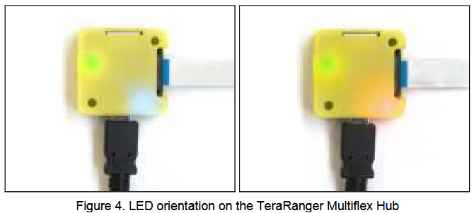
Assembly
Please follow these 5 simple steps illustrating a tutorial on how to connect 8 sensors to the TeraRanger Multiflex Hub.
Step 1. Sensor Positioning
Before connecting, make sure that the sensors are (1) positioned in the correct numeric order and (2) facing the same direction. See Figure 5.
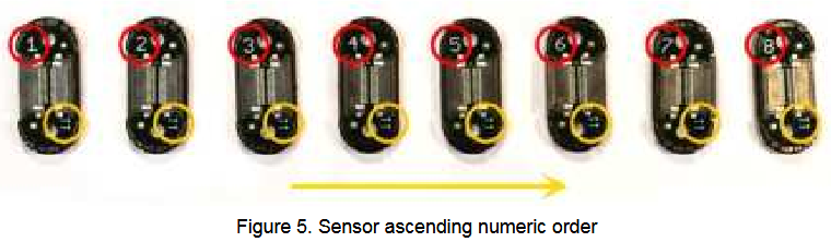
Each sensor is marked with a number (1 to 8), and a direction arrow for connection (Figure 5). Please double-check that the sensor units are placed in ascending order (1, 2, 3, 4, etc.) and that they all face the same direction. In cases when less than 8 sensors are used, always start with the sensor containing the lowest number and then connect subsequent sensors in ascending numeric order.
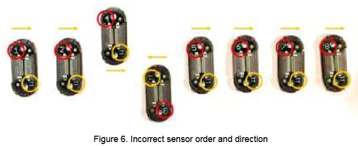
TeraRanger Multiflex will not stream distance data if any of the sensor units are connected in the wrong order or direction. See example in Figure 6.
Step 2. Connecting the Flex Cable to the sensor
Start by plugging the Flex Cable to the sensor’s Flexible Flat Cable (FFC) connector.
Note that each of the FFC connectors need to be manually opened and then closed when connecting the Flex Cables as shown in Figure 7. For easier opening you can gently pull the small locking ‘tabs’ on the sides of the connector before pulling the connector down. You may find this easier with tweezers. The locking mechanism has to be pulled out only a millimeter or less, not entirely! Note that too much force can damage the sensor’s connector. Also, double check that the Flex Cable is plugged in a straight manner to avoid a short-circuit.
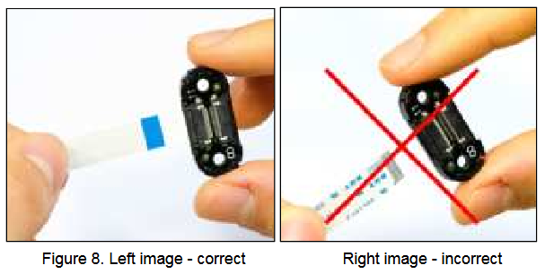
When connecting the Flex Cable, make sure that the side with conductive tracks is facing the sensor’s Printed Circuit Board as shown in Figure 7. Connecting the wrong side of the cable can damage both, the sensor and/or the cable (Figure 8). Once the cable is positioned inside the connector, close the connector by smoothly pushing in the locking mechanism.
Step 3. Connecting sensors to each other
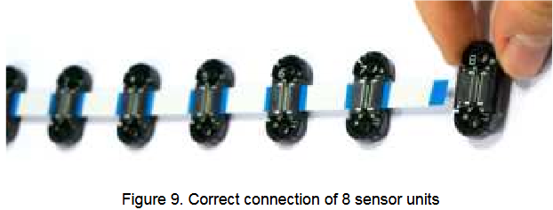
Continue to connect all 8 sensor units together respecting their assigned numerical order (Figure 9).
Step 4. Joining the strip of sensors to TeraRanger Multiflex Hub
Connect the strip of 8 sensors to the TeraRanger Multiflex Hub (Figure 10). The Hub also contains an FFC connector, hence we ask to respect the guidelines on connecting as described in Step 2.
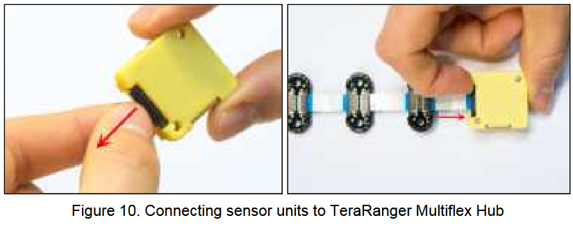
IMPORTANT: Sensor 1 always needs to be directly connected to the TeraRanger Multiflex Hub. The direction arrow must always point away from the TeraRanger Multiflex Hub. In cases when sensor number 1 is not used, please connect sensor with the lowest numeric value.
Step 5. Ready to test!
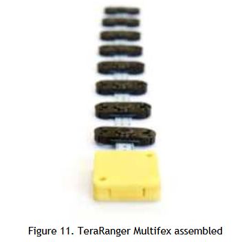
Once fully assembled, the TeraRanger Multiflex is ready for testing on your computer (Figure 11). Use the micro USB cable (provided in the package) to connect the TeraRanger Multiflex Hub with a computer.
Connecting the TeraRanger Multiflex Using a Computer with a Serial Console
TeraRanger Multiflex can interact with any serial console using the following configuration, both for USB, UART and I2C interfaces: 115200 bit/s, 8 data bits, no parity bit and one stop bit.
1. Windows
In Windows you can use terminal emulation software of your choosing, however we suggest you use HTerm (http://www.der-hammer.info/terminal/). Extract the downloaded zip file to the folder of your choice, open it and double click on the “HTerm.exe” document.
Connect the TeraRanger Multiflex to your computer and select the corresponding USB port (click “R” button to refresh the port list). Select values for the following fields: (1) Baudrate, (2) Data Bits, (3) Parity, (4) Stop Bits. For easier readings, select the “CR+LF” option for “Newline at” tab. See Figure 12 for visual instructions.

Once you have selected the USB port and required values, click on the “Connect” button.
The data will now appear in the “Received data” box (Figure 13).
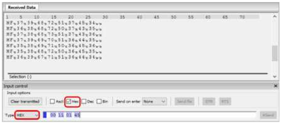
To communicate with the terminal emulation software, you need to send a command in hexadecimal via the “Type” box. First check the “Hex” checkbox and choose the “HEX” Type. Figure X gives the example of the command which allows data to be shown in TEXT mode when 8 sensor units are used. Please see Section 4.1 for basic commands!
2. MacOS
In MacOS we recommend to use a serial port terminal application such as CoolTerm
http://freeware.the-meiers.org/. In the link, please scroll down to find the download file.
Extract the downloaded zip file to^ the folder of your choice, open it and double click on the “CoolTerm.exe” document. The emulation software window should open. Now connect the TeraRanger Multiflex Hub to your computer, and click the “Options” button in the toolbar.

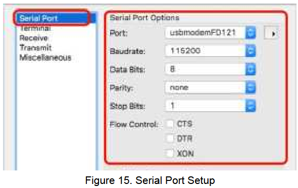
In the “Serial Port” tab please select the corresponding USB port (Click “Re-scan” if the USB is not detected). Select values for following fields (Baudrate, Data Bits, Parity, Stop Bits) as shown in Figure 15.
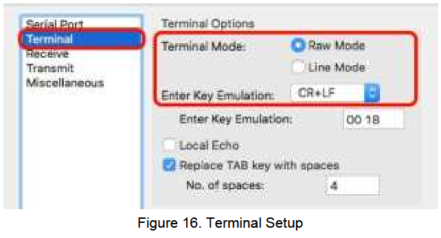
After, in the “Terminal Tab” (Figure 16) make sure the following fields are selected:
- Terminal Mode: Raw Mode
- Enter Key Emulation: CR+LF
Once done, click “OK” to apply changes.
In the toolbar, click the “Connect” button to start the data stream.
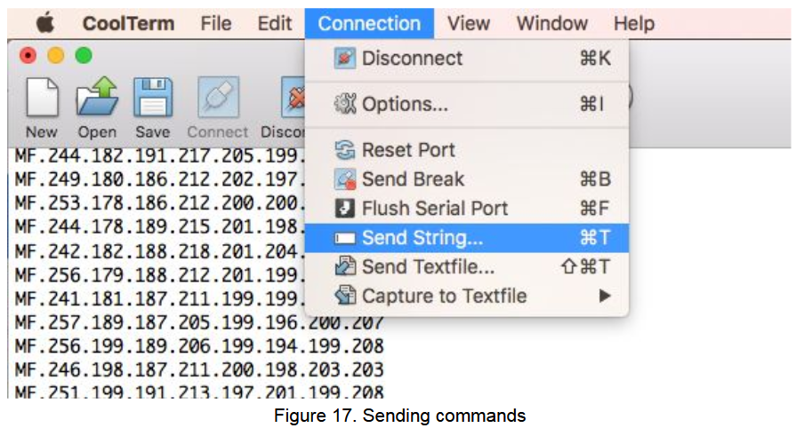
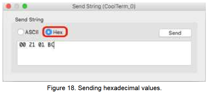
To send commands, in the Menu bar click “Connection” and after “Send string” (shortcut: cmd+T) as shown in Figure 17. Select the “Hex” option as the commands are given in hexadecimal values. See Section 4.1 for basic commands!
You can find more information about using CoolTerm at the following address:
https://learn.sparkfun.com/tutorials/terminal-basics/coolterm-windows-mac-linux
3. Linux
Using Linux Ubuntu, please use Cutecom application for data stream via computer. To do so, first download and then update the application via the terminal software. Use following commands in your Linux shell window:
- sudo apt-get update
- sudo apt-get install cutecom
- cutecom
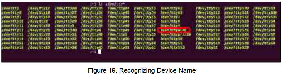
The application automatically runs after launching the command “cutecom”. Next, enter the corresponding Device name by sending the following command in your Linux shell window:
ls /dev/tty*
The device name is usually /dev/tty/ACM0 or /dev/tty/ACM1.
In the main interface, make sure to fill the following fields (Baudrate, Data Bits, Parity, Stop Bits) as shown in Figure 20
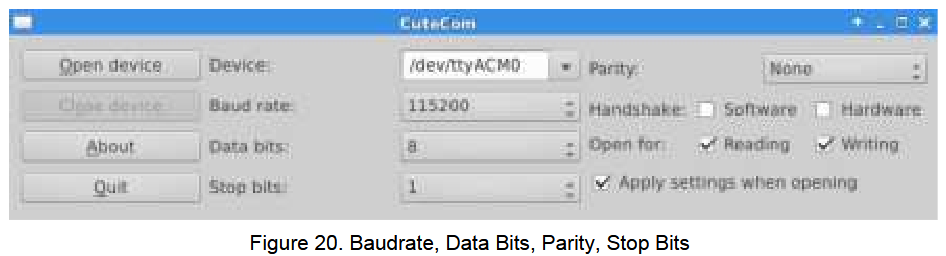
Click the “Open Device” button to start the data stream in millimeters. Note that distance values are separated from each other via the character “\0x09”.
Should you see an error stating that the opening has failed then try sending the following command directly from the linux shell window to grant access to the serial port.
sudo chmod a+rw /dev/ttyACM0
To send commands, the TeraRanger Multiflex uses a Python script. Please follow the ReadMe file (available also under Support section on www.teraranger.com) from the Python script to send the commands.
UART & USB Protocol Description
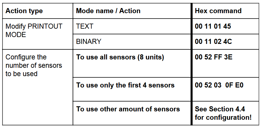
1. Basic Commands (UART & USB)
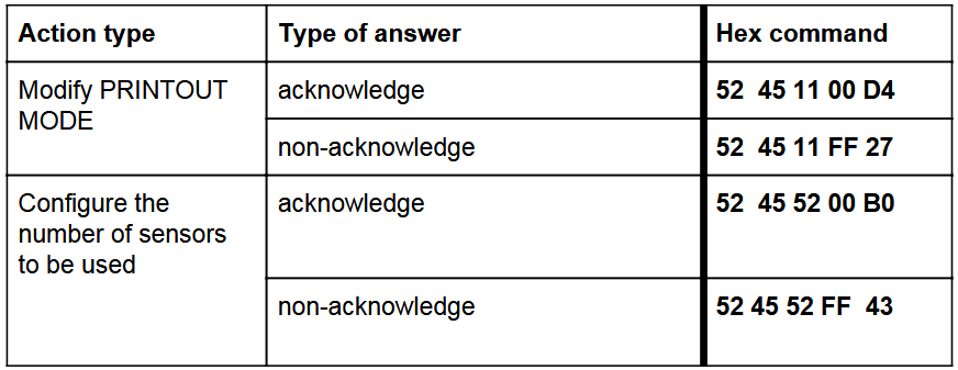
Answer to the basic commands
Each time a command is sent, the user will receive an answer that will inform whether it is an affirmative (acknowledge) or a negative (non-acknowledge) answer.
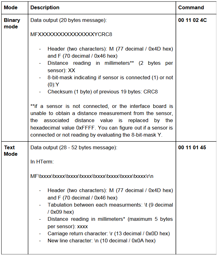
2. Printout Modes
TeraRanger Multiflex firmware supports two printout modes which can be selected by sending the corresponding hexadecimal command to the Multiflex using the serial terminal application (See Section 3 for detailed instructions). Please note that the default mode is binary.

3. Configuring TeraRanger Multiflex Sensors
All commands are a series of bytes. They respect the following format:

The header is one byte: (0 decimal / 0x00 hex)
The command field is a byte that indicates which action you want to perform (example modify the running mode)
The mask field depends on the command. The Data Field contains the data corresponding to the Command to be executed.The data field cannot be empty.
The error checking field contains an 8 bit value which is the result of a Cyclical Redundancy Check (CRC) calculation performed on the message contents.
4. Instructions on Sensor Configuration
The TeraRanger Multiflex can be used with less than 8 sensors. This allows the sensors to work at higher update frequencies. To enable this, the user needs to inform the terminal emulation software about the sensor units to be used by inputting the correct command line. This section shows an example of how to configure 5 sensors (Figure 22).
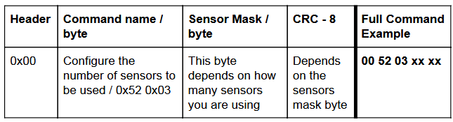
The “Header” and the “Command name” byte values remain always the same: 00 52 03, despite the amount of sensors used in an application!
The following 3 steps provide guidelines on how to calculate the remaining “Sensor Mask” and “CRC” byte values:
1. Calculate the binary byte of operating sensors
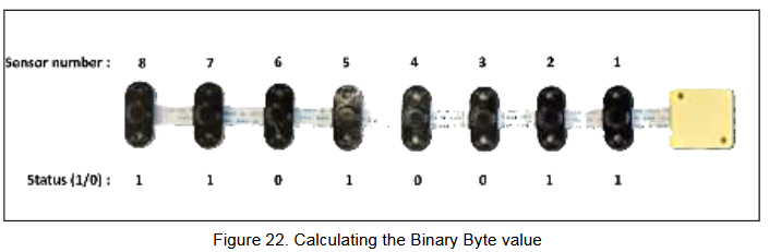
The binary byte consists of 8 values, that represent operating (1) and non-operating (0) sensors. In Figure 22, sensors 8, 7, 5, 2, 1 are operating and 6, 4, 3 are non-operating, which means that the binary byte value (Status) is 11010011
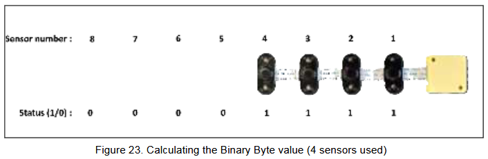
Note: In cases when only the operating sensors will be connected to the TeraRanger Multiflex Hub, the non-operating sensor binary status is not required (Figure 23).
2. Convert binary byte value to a hexadecimal mask byte value
For this, please use the Binary to Hexadecimal converter and find out the mask byte value. After conversion the mask byte value is D3. Now the command should consist of 4 determined bytes: 00 52 03 D3.
3. Calculate the CRC byte of the command by using the CRC byte calculator
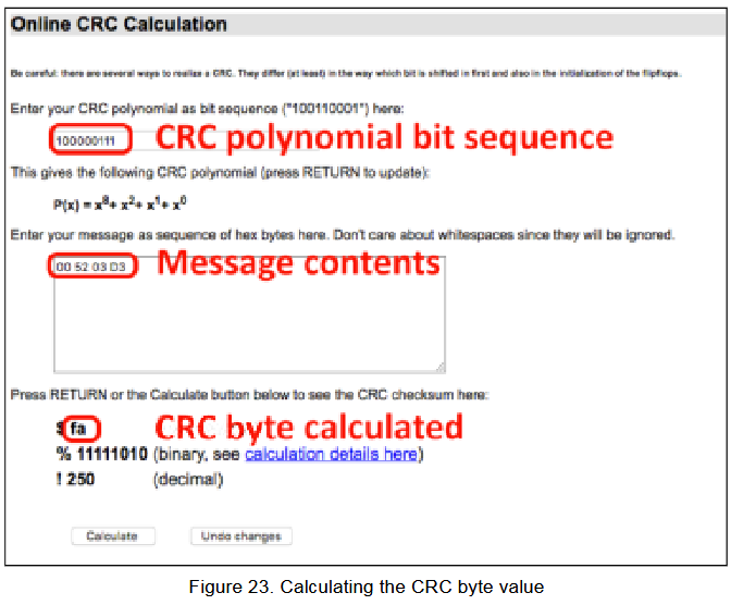
First enter the CRC polynomial bit sequence, which is always: 100000111.
Second, enter the Message Contents, which we have determined before: 00 52 03 D3.
Third, click on “Calculate” to acquire the CRC byte, which in this case is FA.
See Figure 23 for visual instructions.
Finally, we have obtained the full command for configuring the sensor units. The command line to enter in the terminal software is: 00 52 03 D3 FA.

I2C Protocol Description
The TeraRanger Multiflex by default comes in I2C base address (7 bit) 0x55.
Same as when using UART mode, the Multiflex is free running, which means that it will restart a new measurement as soon as the last one is finished. The displayed data via I2C protocol is always updated at the end of a measurement. Nevertheless, it can always be read at any time.
I2C protocol timing diagram

- S: one start bit
- Addr: Multiflex I2C address on 7 bits
- A: one bit of acknowledge
- Cmd: one byte which correspond to what the master wants to read
- Stop: one stop bit
- NA:one bit of non acknowledge
Writing commands to the Multiflex:
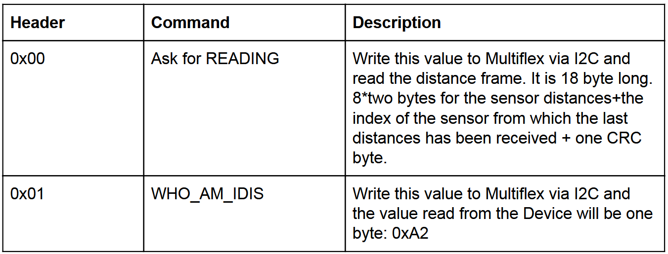
- Send the address byte consisting of a 7 bit base address and the last bit indicating write (‘0’), e.g. 0xAA for base address 0x55. All commands listed in the table below are ‘write operations’, the answer will be in the next read operation for which you have to send the 7 bit address with the read bit set.
- Send the desired command listed in the table below (see table 5.2.3).
- In case the command creates an answer, read it back immediately.
Reading data from the Multiflex:
- Send the address byte consisting of 7 bit base address and the last bit indicating read (‘1’), e.g. 0xAB for base address 0x55.
- Read back the the number of bytes imposed by the command, e.g. eighteen bytes for a distance reading.
Running the TeraRanger Multiflex in ROS
We provide a ROS (Robot Operating System) node which provides a topic to access the TeraRanger Hub data stream. Please note that the TeraRanger Hub has to be configured to work in Binary mode.
You can download the ROS node from:
https://github.com/Terabee/teraranger_hub_multiflex
To use the ROS node you need to:
- Create a ROS Workspace
- Copy the node teraranger_hub_multiflex package into the workspace src directory
- Compile using: catkin_make
- Setup environment: source devel/setup.sh
- Run** using:
rosrun teraranger_hub_multiflex teraranger_hub_multiflex_node _portname:=/dev/ttyACM0
If you want to change a sensor bitmask, run**:
rosrun rqt_reconfigure rqt_reconfigure
** Remember to execute the daemon roscore before running the rosrun command.
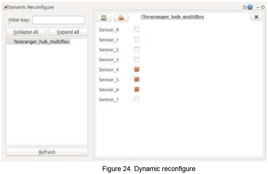
To activate desired sensors set up bit mask by enabling check boxes (Figure 24).
Laser Safety Considerations
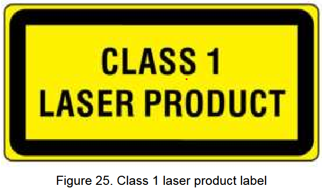
The TeraRanger Multiflex contains a laser emitter and corresponding drive circuitry. The laser output is designed to remain within Class 1 laser safety limits under all reasonably foreseeable conditions including single faults in compliance with IEC 60825-1:2014 (third edition). The laser output should remain within Class 1 limits as long as the TeraRanger recommended device settings are used and any specified operating conditions are respected.
The laser output power must not be increased by any means and no optics should be used with the intention of focusing the laser beam.
Caution: Use of controls or adjustments or performance of procedures other than those specified here may result in hazardous radiation exposure.