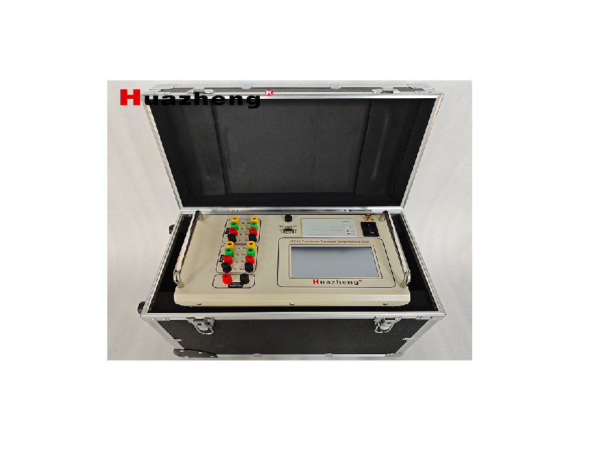
Huazheng HZZH-5 Transformer Parameter Comprehensive Teste

Huazheng Electric Manufacturing (Baoding) Co., Ltd

Welcome to use the products of Baoding Taida Power Equipment Co., Ltd. Please read and save this user manual carefully. If there are any changes to the product’s appearance or color, please refer to the actual product.
Attention
Because the input and output terminals, test columns and so on may have voltage, electric sparks will be generated, be careful of electric shock, avoid the danger of electric shock, pay attention to personal safety!
Safety Instructions
Please read the following safety precautions to avoid personal injury. To prevent possible hazards, only use the product within the specified range.
▼Only qualified technicians should perform maintenance.
▼Prevent fire or personal injury.
▼Use the appropriate power cord. Only use the dedicated and specified power cord. Do not randomly connect or disconnect test leads when they are connected to live terminals.
▼Pay attention to the ratings of all terminals. To prevent fire or electric shock hazards, note all ratings and markings. Before making connections, read the user manual for further information on ratings.
▼Use the appropriate fuse. Only use fuses that comply with the specified type and rating. Avoid contact with exposed circuits and live metal. Do not touch exposed contacts and parts when powered.
▼Do not operate in a humid environment.
▼Do not operate in an explosive environment.
Note: Without the prior permission and written consent of Baoding Taida Power Equipment Co., Ltd., no part of this manual may be reproduced in any form or by any means (including electronic storage and retrieval or translation into other languages). Please read the user manual carefully before using the instrument. Ensuring safety is our responsibility!
Contents
I. Product Introduction
The HZZH-5 Transformer Comprehensive Tester integrates a DC resistance tester, low-voltage short-circuit impedance tester, on-load switch tester, demagnetization tester and transformer ratio tester into one device for testing large power transformers.
II. Product Features
● Product Design
- One-time wiring completes all test items, reducing the workload of on-site testers.
- Equipped with a 7-inch color touch LCD screen for control and display, providing a user-friendly interface.
- Built-in micro printer for on-site printing of test results.
- USB storage function for external storage of test results.
- One isolated RS232 communication interface with standard protocol communication.
- Bluetooth communication module with standard protocol wireless communication.
- High-reliability RS485 bus for internal communication.
- Isolated circuit design to eliminate interference between test functions; hardware and software filtering to improve anti-interference capability; good grounding and shielding measures to enhance overall anti-interference capability.
● DC Resistance Test
- Three-phase simultaneous testing and automatic magnetization.
- High and low voltage current and potential test leads can be connected to the transformer at once, eliminating the need to switch test leads during the test.
- For star-connected windings with a neutral point, the A0, B0, and C0 phase resistances can be tested simultaneously, significantly saving test time.
- For an internally delta-connected three-phase five-limb transformer, the automatic excitation method can be used during low-voltage side testing, which offers fast testing speed.
- Displays and prints all test data of high, medium, and low voltage windings, automatically calculates three-phase unbalance, and prints resistance values converted to rated temperature.
- Comprehensive back EMF protection.
● Short-Circuit Impedance Test
- Single-phase 220V power supply is used to automatically apply current to the AB, BC, and CA windings ofthe transformer, synchronously collect data, and convert it to the rated impedance percentage.
- For three-phase transformers with Y/△, Y/Y, △/Y connections, the wiring can be connected once, and the three-phase measurement can be selected to automatically measure the data and calculate the impedance value and impedance error.
- When using the single-phase method for three-phase transformers, input 1/3 of the rated capacity.
- Displays and prints all test data of the transformer.
- The device can permanently store test data.
● On-load Switch Test
- Three independent constant current sources.
- Powerful functions, including transition waveform, transition time, transition resistance, and three-phase synchronization measurement.
- Intelligent testing and result analysis.
- Displays and prints the test waveform of the transformer’s on-load switch.
- The instrument can permanently store test waveforms.
- Equipped with an automatic discharge circuit and overvoltage protection circuit.
● Transformer demagnetization Test
- Fast demagnetization with obvious effects.
- Fully automatic and manual demagnetization functions, with a progress bar and percentage displayed during demagnetization.
- Comprehensive back EMF protection.
- Suitable for eliminating residual magnetism in large power transformers of 35kV and above before operation.
- Automatic current stabilization judgment, data acquisition, and processing functions.
- One-button operation, strong anti-interference ability.
- Can directly use the current leads of the DC resistance test, convenient for use with the DC resistance test.
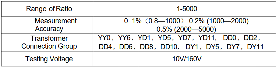
● Transformer Ratio Test
- Chinese/English menu prompts, simple and convenient operation.
- Three-phase testing only requires inputting the high-voltage side connection method to automatically measure the group.
- Capable of both single-phase measurement and automatic testing of three- phase windings. The connection group can be arbitrarily selected, completing the measurement of parameters such as the ratio, error, and connection group of AB, BC, and CA phases in one go.
- Protection function for high and low voltage reverse connection.
- Fast testing speed, completing single-phase testing in 15 seconds.
- Protection functions for transformer short-circuit and inter-turn short-circuit
Measurement Parameters
DC Resistance: DC resistance is the resistance presented when a DC voltage is applied across the component, i.e., the inherent, static resistance of the component. When AC and DC are applied to a coil, the resistance presented is different. When AC is applied, the coil has reactance in addition to DC resistance. Since the DC resistance of transformers, mutual inductors, generators, and motors is small, appropriate methods must be used to measure it to reduce errors. Kelvin four- terminal sensing (4T sensing) is a resistance measurement technique that uses separate pairs of current-carrying and voltage-sensing electrodes, allowing for more accurate measurements compared to traditional two-terminal (2T) sensing. The key advantage of four-terminal sensing is the separation of current and voltage electrodes, eliminating the impedance of wiring and contact resistance.
Short-Circuit Impedance: The short-circuit impedance of a transformer, also known as the impedance voltage, represents the voltage loss (in percentage) caused by the transformer’s own impedance when the rated current passes through it.
Transformer demagnetization: During the operation of a power transformer, a steady-state magnetic flux is generated inside it. When the transformer is de-energized, due to the conservation of magnetic flux, the steady-state magnetic flux does not disappear immediately but retains a residual magnetic flux equal in magnitude and polarity to the steady-state magnetic flux at the last moment. On the other hand, due to the inherent hysteresis phenomenon of ferromagnetic materials, residual magnetism will also remain in the iron core after operations such as voltage ratio and DC resistance measurement. Due to the presence of residual magnetism, when the transformer is put into operation, the residual magnetism in the iron core causes the transformer core to saturate for half a cycle, generating a large number of harmonics in the excitation current. This not only increases the reactive power consumption of the transformer but also causes a large primary current, damaging the transformer, and may cause secondary peak voltage, damaging the load or the insulation of the transformer itself. Moreover, it may cause the relay protector to malfunction, resulting in certain economic losses. Therefore, we must perform demagnetization work before the transformer is put into operation to ensure the safe and normal operation of the transformer.
Transformer Ratio: Transformer Turns Ratio refers to the voltage ratio between the primary winding and the secondary winding of a transformer. According to relevant national standards, the transformer turns ratio test is a mandatory item during the production, user handover, and maintenance testing of power transformers. This test effectively monitors the quality of transformer products during manufacturing and usage, preventing issues such as inter-turn short circuits, open circuits, incorrect connections, and internal or contact faults in the tap changer.
V. Instrument Panel Introduction
1. Front Panel
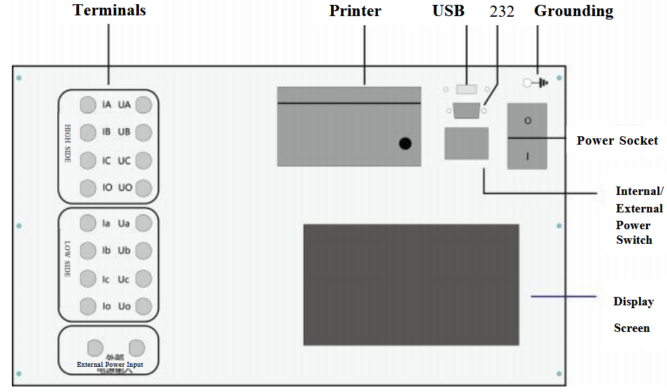
- Power Socket: With a built-in switch and fuse compartment, fuse: 10A.
- Grounding: Connect to the ground during use.
- USB Port: Can connect to a mouse, USB flash drive, and other USB devices.
- RS232 Port: Connect to an external printer.
- Internal/External Power Switch: When using the low-voltage short-circuit impedance test, switch between the internal power supply and external voltage regulator output.
- Display Screen: Touch screen, controls the instrument status and displays various parameters.
- Printer: Used to print various test parameters.
- Terminals: Used to connect test leads for different functions.
2. Terminal Panel
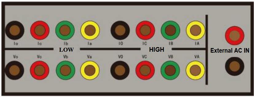
External AC Input: Connect to the voltage regulator terminals.
High Voltage: “IA IB IC IO” are current terminals, “VA VB VC” are voltage terminals.
Low Voltage: “Ia Ib Ic Io” are current terminals, “Va Vb Vc” are voltage terminals.
V. Main Technical Specifications
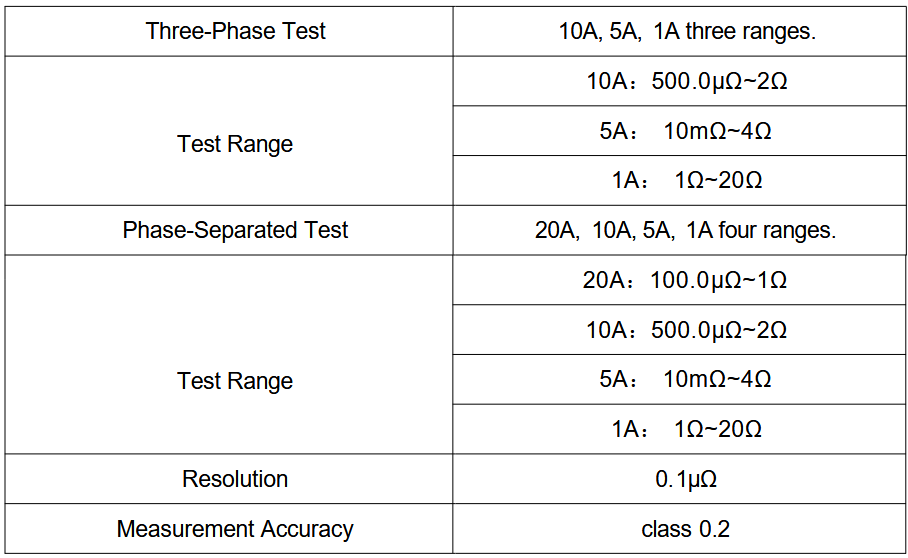
1. DC Resistance Test
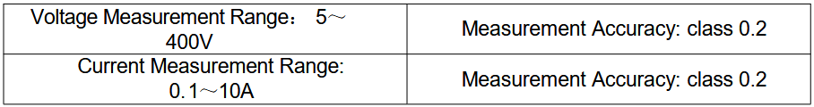
2. Short-Circuit Impedance Test
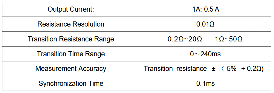
3. On-load Switch Test
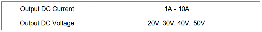
4. Transformer demagnetization Test
5. Transformer Ratio
VI. Operation Procedure
1. Preparation and Wiring
Before using the instrument, check the current working environment to ensure safety before proceeding with wiring.
To ensure your safety and the safety of the equipment, please check the reliability of the grounding wire.
● DC Resistance Test Wiring Diagram
- Connect the instrument to an external AC 220V power supply using the power cord, and connect the grounding terminal to the ground using the grounding wire.
- For two-winding transformers, connect the four test clips on the high-voltage terminal (yellow, green, red, black) to the high-voltage side A, B, C, O bushings. If there are only A, B, C bushings, leave the black clip unconnected. Connect the four test clips on the low-voltage terminal (yellow, green, red, black) to the low-voltage side a, b, c, o bushings. If there are only a, b, c bushings, leave the black clip unconnected.
- For three-winding transformers, after testing the high and low voltage windings, connect the four test clips on the high-voltage terminal to the medium-voltage side for testing.
- For single-phase transformers, connect the yellow and black test clips on the high-voltage terminal to the high-voltage side of the single-phase transformer, and connect the yellow and black test clips on the low-voltage terminal to the low-voltage side of the single-phase transformer.
- The dedicated test leads provided with the instrument have the current and potential leads designed into the same clip, so just connect them.
Note: The instrument uses three-channel DC resistance testing, so the leads can be connected at once. When testing the medium-voltage winding, connect the medium-voltage test leads to the high-voltage terminal of the instrument to test the medium-voltage DC resistance.
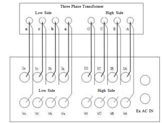
● Short-Circuit Impedance Test Wiring Diagram
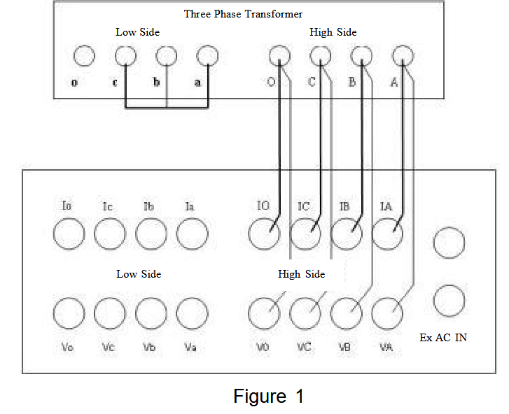
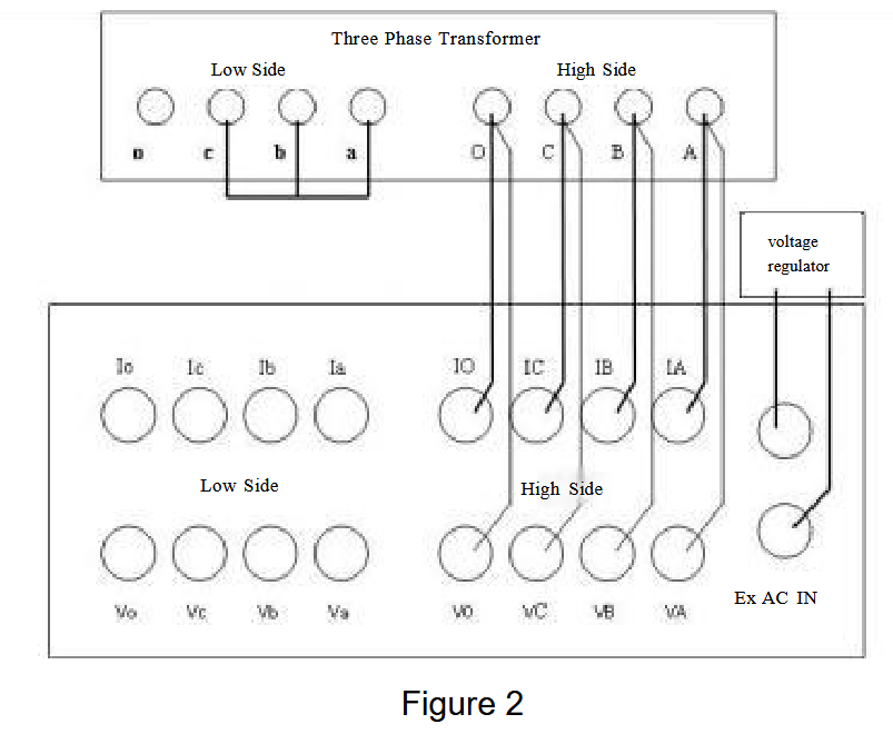
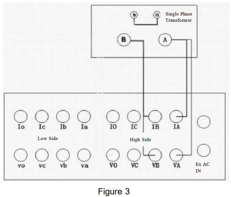
Figure 1: Using the internal power supply for short-circuit impedance testing (set the panel switch to internal power).
Figure 2: Using an external voltage regulator for short-circuit impedance testing (set the panel switch to external power).
Figure 3: Wiring diagram for single-phase transformer testing (for single-phase measurement, the output terminal is the high-voltage side “AO” phase).
For three-phase measurement, the O phase can be connected or not, which will not affect the test results.
When testing “medium-low”, just connect the high-voltage side leads to the medium voltage.
● On-load Switch Test Wiring Diagram
● Transformer Demagnetization Test Wiring Diagram
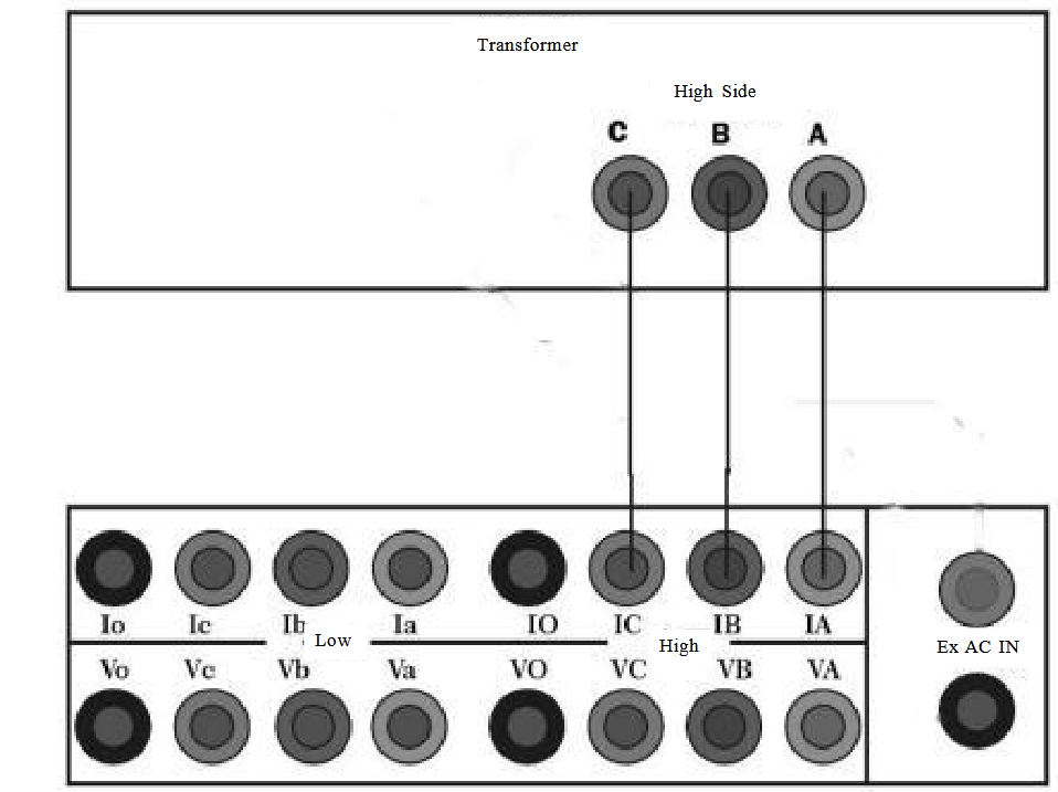
For single-phase transformers: Connect the high-voltage side test leads to the transformer bushings and the instrument.
For three-phase transformers: If demagnetizing after a DC resistance test, demagnetize the high-voltage side ab, bc, and ca separately. The demagnetization output is not polarity-sensitive.
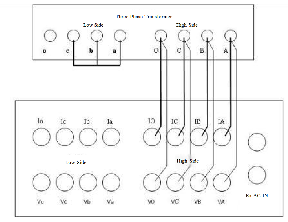
● Transformer Ratio Test Wiring Diagram

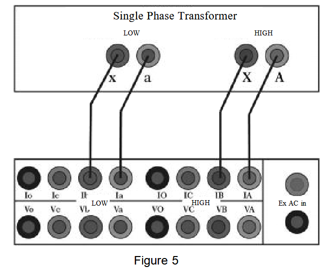
Note: Figure 4 shows the wiring method for the three-phase transformer in the turns ratio test function. The high-voltage side A, B, and C are connected to IA, IB, and IC respectively, while the low-voltage side a, b, and c are connected to Ia, Ib, and Ic respectively. Figure 5 shows the wiring method for the single-phase transformer. The high-voltage side A and B are connected to IA and IB respectively, while the low-voltage side a and x are connected to Ia and Ib respectively.
Operating Instructions
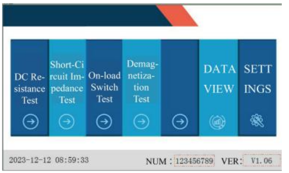
Boot – up: Connect the AC220V power supply to the instrument, connect the transformer bushing and the instrument with test leads, and connect the grounding terminal of the instrument to the ground with the grounding wire. After connecting the power cord and turning on the switch, enter the menu interface.
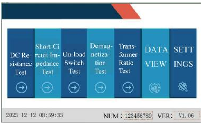
System Settings : On the instrument test interface, touch “System Settings” lightly to enter the system settings interface. Enter the relevant parameters according to the prompts, and then touch “Confirm” lightly to return to the instrument option interface.
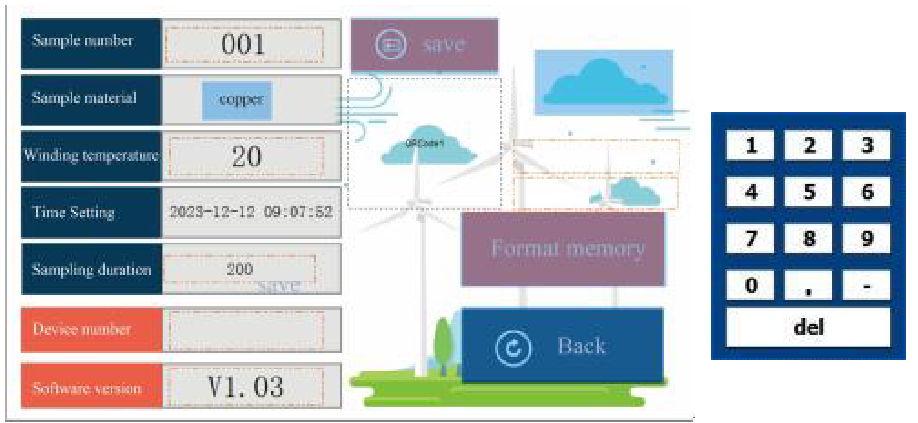
Set the Test Sample Number: Touch the white rectangular area after the test sample number lightly, and a numeric keypad will pop up to set the name for data storage. Touch the [0 – 9], [ – ], [.] buttons to set the test sample name freely. If you want to modify the name, touch the [del] button, and the current number will be erased. Touch any area other than the numeric keypad to exit the setting.
Set the Winding Material: Touch the white rectangular area after the winding material lightly, and you can switch the winding material between copper and aluminum. Touch other areas to exit the current setting.
Set the Test Temperature: Touch the white rectangular area after the test temperature lightly, and a numeric keypad will pop up (refer to the picture for setting the test sample number). Enter the temperature value of the test sample by touching the [0 – 9], [ – ], [.] buttons. If you want to modify the number, touch the [Del] button, and the current number will be erased. Touch any area other than the numeric keypad to exit the current setting.
Set the Time: Touch the white rectangular area after the test temperature lightly, and a numeric keypad will pop up (refer to the picture for setting the test sample number). Set the instrument clock by touching the [0 – 9] buttons. If you want to modify the number, touch the [Del] button, and the current number will be erased. Touch any area other than the numeric keypad to exit the current setting.
Set the Acquisition Duration: Touch the white rectangular area after the recording duration lightly, select the required test duration, and touch the option to be set. Touch any area other than the numeric keypad to exit the current setting.
VII. Pre-Test Precautions
- Please follow the instructions in this manual for wiring and operation.
- The grounding terminal or the grounding end of the power cord should be reliably grounded nearby.
- For DC resistance testing, select the appropriate test current according to the resistance range of the test object.
- Although the instrument has a discharge protection circuit, try to avoid abnormal situations such as test clip dropped down or power failure during the test.
- For different transformers, select the appropriate current range for demagnetization. For special transformers such as converter transformers, manual demagnetization must be used at the 1A current range.
- During demagnetization, the instrument will apply an AC 220V voltage to the winding. Please ensure that other windings are handled safely.
- In case of special circumstances, please turn off the power directly and wait for a while before removing the test leads.
- Ensure that the instrument is reliably grounded before testing.
- When wiring, please ensure that the high-voltage and low-voltage leads are not reversed.
- Before testing, please enter the correct parameter settings. The group number and the tested transformer must be consistent.
- If the rated ratio is not entered, the test result will only display the measured ratio value, not the error.
- Note: Do not reverse the high and low voltage connections ofthe transformer!
VIII. Test Procedure
1. DC Resistance Test
On the instrument test interface, touch “DC Resistance” to enter the DC resistance interface.
Set the correct parameters for winding temperature, conversion temperature, and winding material.
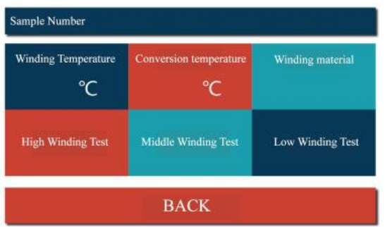
Select “High winding Test”, “Middle winding Test”, or “Low winding Test” as needed.
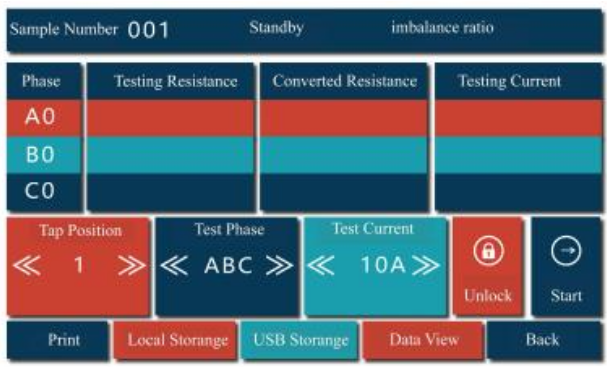
After pressing the high (medium/low) winding test button, the instrument enters the test interface.The status bar will display the current test progress in real-time.
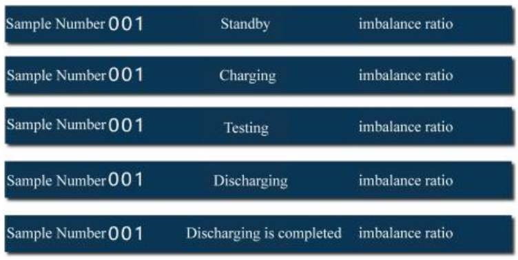
When you enter the test interface but haven’t started the test yet, the title bar will show the standby status.
After starting the test, during the process of stabilizing the test current, the status bar will show the charging status.
After the current stabilizes, the current and the measured resistance value will be displayed in real – time, and the status bar will show the testing status.
When you click the stop button, the status bar will show the discharging status.
After the discharging is completed, the status bar will show that the discharging is completed, and then it will enter the standby status.
After the data stabilizes, you can perform the following operations:
- For the test phase, the selectable options are A0, B0, C0, AB, BC, CA, and ABC.For the single – phase test, you can select A0, B0, C0, AB, BC, and CA phases.For the three – phase test, select the ABC phase. At this time, the maximum test current is 10A.For the magnetic – assisted test, select AB, BC, and CA phases. In the low – voltage test, the magnetic – assistance button will be automatically displayed. Click the box after the magnetic – assistance button, and a checkmark appears, indicating that the magnetic- assistance function is successfully selected.
- For the test current, the selectable options are 1A, 5A, 10A, and 20A.
After selecting the required test phase and current, touch “Start” to enter the test state. After the data stabilizes, you can perform the following operations:
![]()
Local Storage: Click the local storage button to save the current test value. The status bar will show that the storage is successful. When you need to test the DC resistance of other taps, you don’t need to stop the discharging. Just adjust the tap position of the transformer directly. The instrument will automatically measure the resistance value of the current tap. After the data stabilizes, touch local storage to save the data of the current tap position.
USB Storage: Click the USB storage button to save the current test value to the USB flash drive
Lock: Click the lock button to fix and display the current test data.
Print: Click the print button to print the test data of the current tap.
After the test is completed, click the stop button to stop the test. After the discharging is completed, click the return button to return to the previous interface.
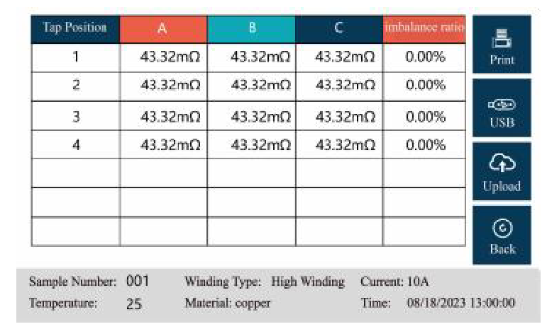
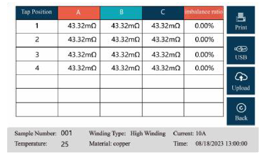
Data View: Click the data view button to view the test data of all taps. In this interface, you can perform printing and USB storage. Click the return button to return to the test interface.
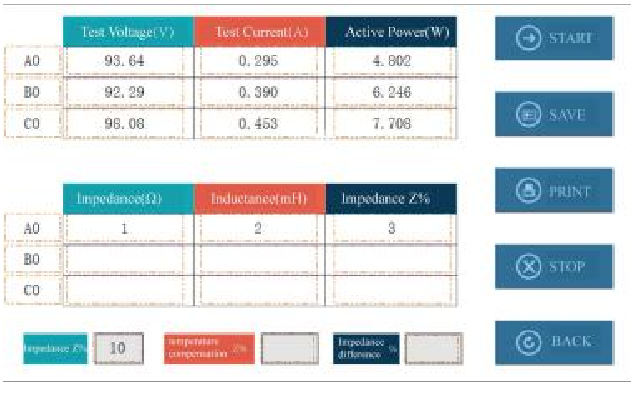
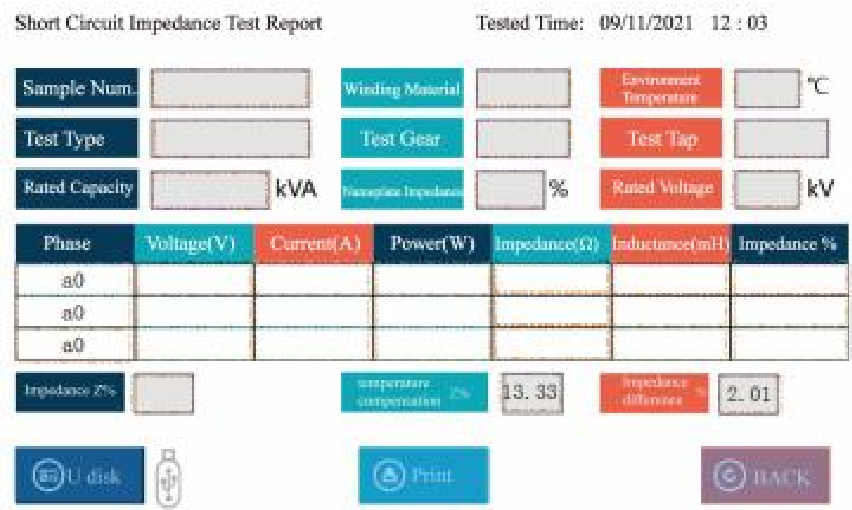
1. On the instrument testing interface, touch “Short Circuit Impedance” to enter the short – circuit impedance setting interface. Fill in the relevant parameters according to the prompts (refer to the instruction manual). After completion, click “Single – Phase Test” or “Three – Phase Test” according to the test item. The single – phase test runs automatically. For the three – phase test, you can choose three – phase automatic or three
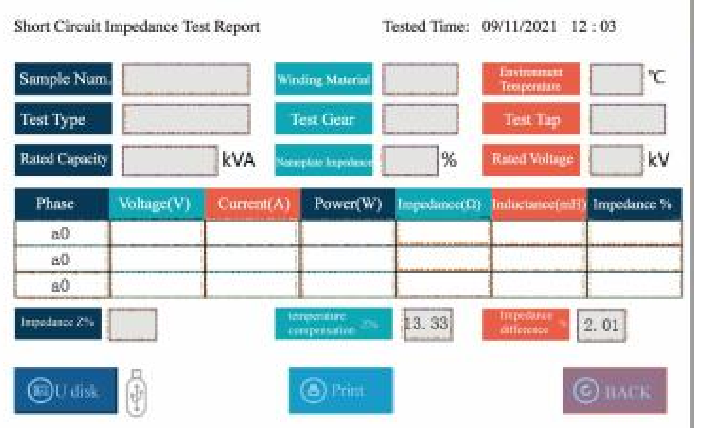
– phase manual. In the automatic mode, the short – circuit impedences of phases AB, BC, and CA are measured in sequence. In the manual mode, you need to manually select the phase to be measured. After the test is completed, the impedance value and impedance error will be automatically calculated. You can connect a printer. Touch “Print” to print the current test data, touch “Save” to save the data to the internal memory of the instrument (a “Storage Successful” prompt will appear when saving), and touch “Exit” to return to the setting interface.
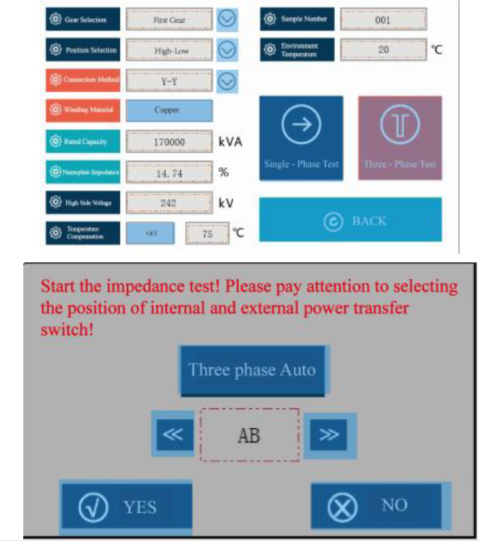
Rated Capacity: The capacity marked on the transformer nameplate.
High Side Voltage: The voltage of the test side (high – voltage, medium – voltage).
Nameplate Impedance: The impedance value marked on the transformer nameplate (expressed in percentage format). Connection Method: The connection method of the transformer coils.
Position Selection: High – Low, High – Medium, Medium – Low.
Gear Selection: First Gear, Rated Gear, Last Gear (highest voltage tap, rated voltage tap, lowest voltage tap).
View Data: Click the view data button to view the test data of all taps.
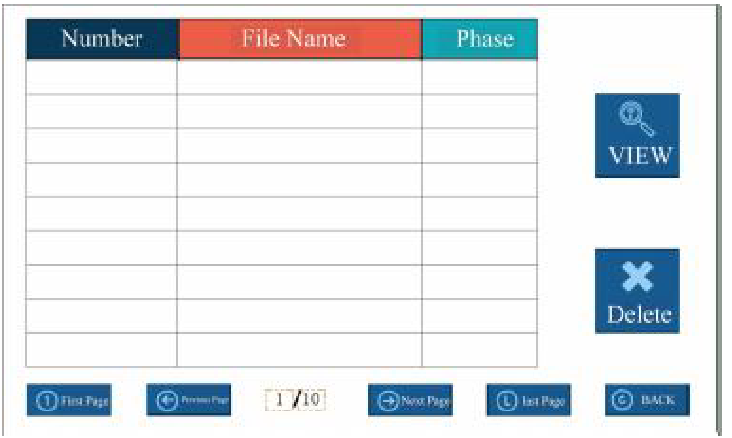
In this interface, you can select the required test number. After opening it, you can perform relevant operations. Click the return button to return to the test interface.
3. On Load Switch Test
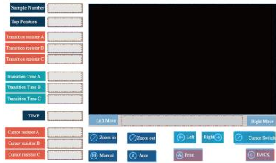
On the instrument testing interface, touch “On Load Switch” to enter the On Load Switch waiting to be tested interface. Touch “+” and “-” to select the tap position of the switch, and touch “+” and “-” to adjust the size of the starting setting value. (Note: Generally, there is no need to change the starting setting value. The smaller the starting value, the more sensitive it is.)
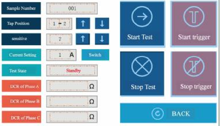
Touch “Start Test”, and a prompt of “Confirm” and “Cancel” will appear. After confirmation, the instrument starts the test. After the data stabilizes, touch “Start Trigger” to change the tap position of the On Load Switch of the transformer, and then the relevant parameters of the On Load Switch test can be measured. You can analyze the waveform. Touch the waveform area to pop up the left cursor. Touch “Cursor Switch” to pop up the right cursor. The cursor can move freely in the waveform. Touch “Left Move” and “Right Move” to fine – tune the cursor position. Touch “Average Resistance” to display the average resistance value of the current cursor. Touch “Transition Time” to display the transition time between the left and right cursor segments. Touch “Synchronism” to display the synchronous time between the waveforms. Touch “Print” to print the current test waveform, transition time, transition resistance, and synchronous time. The instrument will automatically store the tested waveform in the instrument. Touch “Exit” to return to the On Load Switch test interface.
Touch “Start Trigger” to continuously test other taps of the On Load Switch test. Touch “Stop Test” to stop the output of the instrument and discharge.
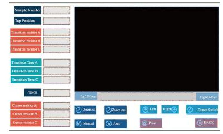
Stored Resistance: Store the resistance values at the positions of the three -phase cursors respectively.
Average Resistance: The average resistance value at the position of the current cursor.
Transition Time: Display the transition times of the three – phase left – and right – cursor segments respectively.
Synchronism: Display the synchronous time between the three – phase waveforms.
Print: Print the cursor resistance value, average resistance value, and stored resistance value respectively.
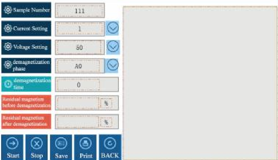
4. Transformer Demagnetization: Test On the instrument testing interface, touch “Demagnetization Test” to enter the following interface.
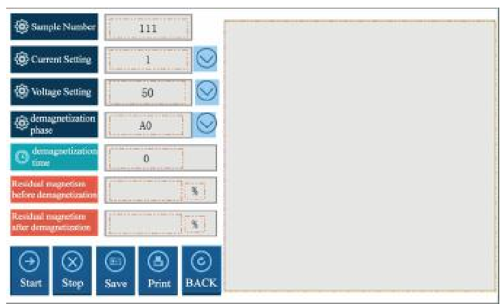
After clicking “Start Test”, the device will demagnetize the test sample. The demagnetization time is recorded, and the residual magnetic flux before and after demagnetization is displayed as a percentage of the residual magnetic flux of the test sample respectively. When data appears for the residual magnetic flux after demagnetization, it indicates that the demagnetization is completed. You can save and print the data.
The data management interface can be used to view and print the saved historical demagnetization data.
Note: When there is a wiring error, such as reversing the high – and low – voltage sides or short – circuiting the primary and secondary sides, the instrument will pop up a warning box. At this time, please check the wiring. After the wiring is correct, perform the above operations.
5. Transformer Ratio Test
On the instrument testing interface, touch the “Transformer Ratio Test” to enter the diagram interface.
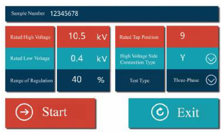
1. Single-Phase Test
After connecting the test leads, select Single-Phase from the three wiring methods below the connection diagram. Input the rated turns ratio. If an incorrect ratio is entered, the ratio error and the current tap position will not be displayed correctly. Click the Start button and wait for the test results to appear. If you need to pause during the test, click the Stop button. Click Exit to leave the turns ratio test interface.
2. Three-Phase Test
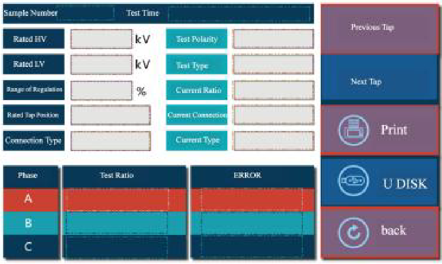
After connecting the test leads, select Three-Phase Y (if the high-voltage side is star-connected) or Three-Phase D (if the high-voltage side is delta-connected) from the three wiring methods below the connection diagram, based on the high-voltage side connection method of the three-phase transformer. Input the rated turns ratio as indicated on the nameplate. If an incorrect ratio is entered, the ratio error and the current tap position will not be displayed correctly. Click the Start button. The current vector group will be displayed first, followed by the current three-phase turns ratio values. Wait for the test results to appear. If you need to pause during the test, click the Stop button. Click Exit to leave the turns ratio test interface. The completed test interface is shown in the figure below:
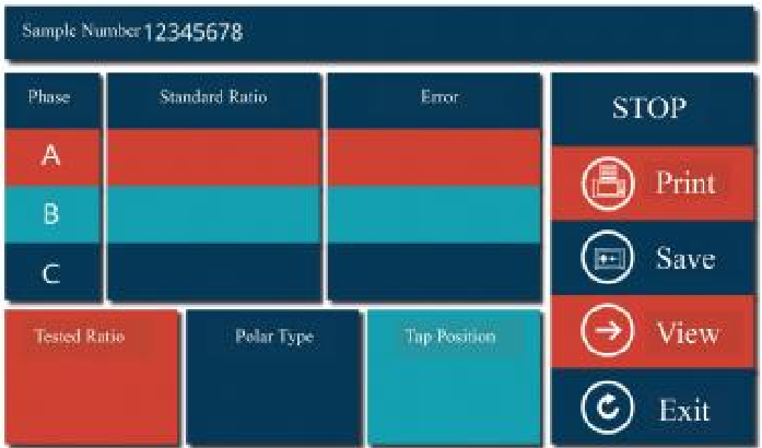
Note: If a wiring error occurs, such as reversing the high and low voltage connections or short-circuiting the primary or secondary side, the instrument will pop up a warning box. In this case, please check the wiring and ensure it is correct before proceeding with the above operations.
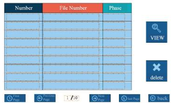
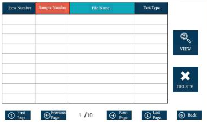
IX. Data Management and Storage
The instrument records test data in the format of “time – transformer number”. All the test data collected on the same day are stored in a file directory named after the date, which is convenient for searching.
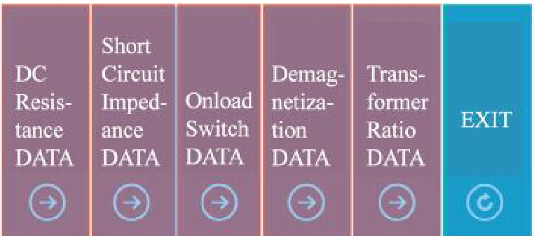
- Touch “DATA VIEW” to enter the test item interface, and select the test item you want to view.
- Touch the corresponding item to enter the storage directory, and select the file you want to view or delete for operation.
- Touch “DC Resistance DATA”, and you can enter the DC resistance data management interface. Here, you can view all the saved data or print all the saved data at once.
4. Touch “Short Circuit Impedance DATA” to enter the short – circuit impedance data management interface. You can view all the saved data or select the gear you want to print and print the data.
5. Touch “On Load Switch DATA” to enter the On Load Switch data management interface. Select the waveform you want to view, and touch “Waveform Analysis”. You can open the waveform analysis interface to analyze or print the waveform. In the waveform analysis interface, the “Zoom In/Out” buttons can be used to adjust the waveform horizontally. In the manual mode, you can select the corresponding cursor for point – by – point calculation.
6. Touch “Demagnetization Data” to enter the demagnetization data directory. Select the data you want to view to check the corresponding experimental results.
7. Touch “Turns Ratio Data” to enter the demagnetization data directory. Select the data you need to view, and you can check the corresponding test results.
8. Insert a USB flash drive. Touch “Saved Test Data” (it can store all the data of one day named after the time, such as June 4, 2013; or it can store the data of a specific transformer named after the test sample number). After it turns into a blue – bordered box, touch “Save to USB” and a “Storage Successful” prompt will appear, indicating that the selected data has been successfully saved to the USB flash drive.
X. Precautions
- To ensure the safety of personnel and equipment, we repeatedly remind users to pay attention to the grounding of the instrument and the discharging after the test.
- Before connecting the test wires, make sure that the instrument is not in the working state. The device under test should be disconnected from the power supply and discharged manually. Only after ensuring safety can the wiring operation be carried out.
- The instrument should be stored in a place where the room temperature is -10 C to 50 C, the relative humidity is 20% – 90%RH, and there are no corrosive gases and harmful substances in the air.
- Before using this instrument, be sure to read this manual carefully. The instrument operator should have some common sense of electrical equipment or instrument operation. This instrument can be used indoors and outdoors, but it should be protected from rain and strong vibration.
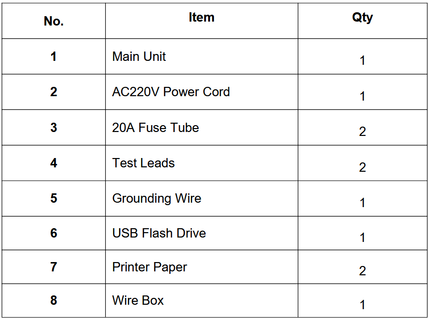
XI. Packing List