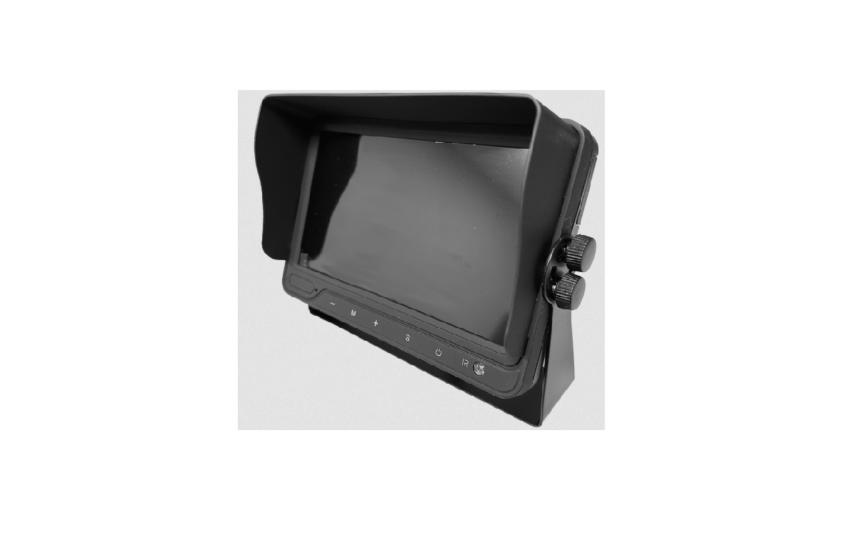
Prorenfort CM-BM0700 Wired Monitor Quad Split Screen Instruction Manual

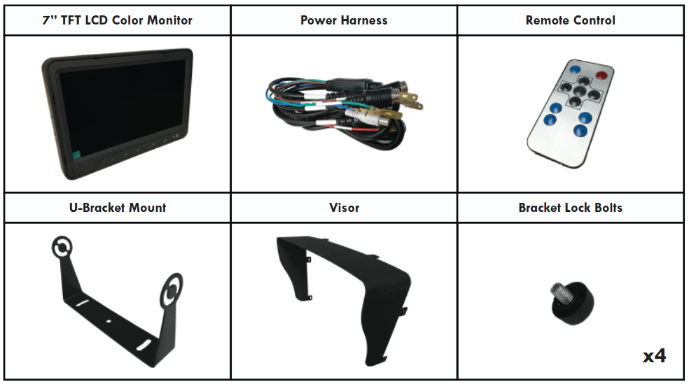
Product Contents Included
Preparing For Installation
Ensure that you read [SAFETY FIRST] on the next page (pg.2) before proceeding. Performing a bench test is recommended before installation to ensure that all product components (see below) are properly working.
IMPORTANT!! Installation instructions MUST be read before installing the product. Failing to do so will void manufacturer warranty.
Any Camera System is intended to be installed as a supplement aid to any existing safety features in your vehicle. In some places, it may be unlawful for a person to drive a motor vehicle equipped with a monitor located in visible sight to driver while vehicle is in operation.
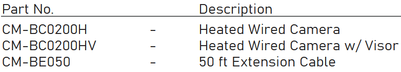
Component List (Sold Seperately):
SAFETY FIRST – READ THIS INFORMATION BEFORE INSTALLATION
Proper installation of this product requires the installer to have a good understanding of automotive electronics systems and procedures.
All products must have proper fuse installed.
If mounting this product requires drilling holes, the installer MUST be sure that no vehicle components or other vital parts could be damaged by the drilling process. Check both sides of the mounting surface before drilling begins. Also de-burr any holes and removes any metal shards or remnants. Install grommets into all wire passage holes.
If this manual states that this product may be mounted with suction cups or magnets, clean the mounting surface with 50/50 mix of isopropyl alcohol and water, then dry thoroughly.
Do not install this product or route any wires in the deployment area of your air bag. Equipment mounted or located in the air bag deployment area will damage or reduce the effectiveness of the air bag, or become a projectile that could cause serious personal injury or death. Refer to your vehicle owner’s manual for the air bag deployment area. The user/installer assumes full reponsibility to determine proper mounting location based on providing ultimate safety to all passengers inside the vehicle. Install only where vehicle manufacturer recommends.
For this product to operate at optimum efficiency, a good electrical connection to chassis ground must be made. The recommended procedure requires the product ground wire to be connected directly to the NEGATIVE [-] post. At a minimum, it may be attached to a solid metal body or chassis part that will provide an effective ground path as long as the product system is to be used.
If this product uses a device to activate or control this product, make sure that this control is located in the area that allows both the vehicle and the control to be operated safely.
Do not attempt to activate or control this device in a hazardous driving situation.
It is recommended that these instructions be stored in a safe place and referred to when performing maintenance and/or reinstallation of this product.
FAILURE TO FOLLOW THESE SAFETY PRECAUTIONS AND INSTRUCTIONS COULD RESULT IN DAMAGE TO THE PRODUCT OR VEHICLE
AND/OR SERIOUS INJURY TO YOU AND YOUR PASSENGERS!
USAGE
The Camera System is designed to provide driver with additional support in avoiding damage or injury. This is not a substitute for safe, proper or legal driving. Area displayed is limited and does not display the entire panorama that is behind you.
This is a high precision product. Electric shock or malfunction may occur if this product is installed incorrectly. Ensure product is firmly affixed before use. Dropping the unit may cause possible mechanical/electrical failure.
Rear View system should only be used when the vehicle is operating in reverse.
An unfused installation may cause damage to equipment, fire, or injury to you or others. Ensure that a fuse is installed.
MAINTENANCE
Use only soap and water to clean the outer lens. Use of other chemicals could result in premature lens cracking [crazing] and discoloration. Lenses in this condition have significantly reduced effectiveness and should be replaced immediately. Inspect and operate this product regularly to confirm its proper operation and mounting condition. Do not use a pressure washer to clean this product.
Environmental conditions for installed locations must be dirt-free, out of direct sunlight and high temperature.
IMPORTANT ELECTRICAL WARNINGS!!
DO NOT use a cigar lighter socket as a power source for this or any electrical accessory! Use a 12 volt accessory power port or auxiliary power outlet of sufficient capability. Do not exceed the manufacturers’ power rating for the selected port/outlet!
DO NOT pull on the power plug wires when removing the plug from the outlet! To remove, firmly grasp the power plug housing and pull.
ANY DEVIATIONS FROM THE ABOVE ELECTRICAL GUIDELINES WILL VOID THE PRODUCT WARRANTY.
IMPORTANT! It is the responsibility of the installation technician to make sure that the installation and operation of this product will not interfere with or compromise the operation or efficiency of any vehicle equipment!
IMPORTANT! Before returning the vehicle to active service, visually confirm the proper operation of this product, as well as all vehicle components and equipments.
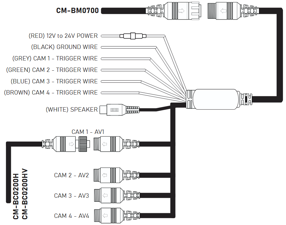
Wiring Diagram
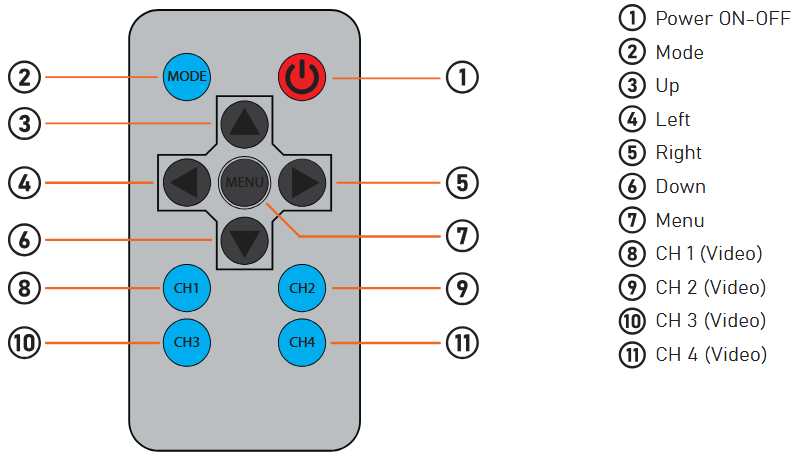
Remote Control
Installation Guide
The CM-BM0700 will only work with products listed in the [Component List].
WARNING!! KEEP ALL CABLES AWAY FROM HOT OR MOVING PARTS THAT COULD CAUSE ELECTRICAL INTERFERENCE.
STEP 1: Choose your desired monitor and camera locations based on safety procedures.
STEP 2: Feed all cables through the vehicle. If required, drill a [20mm or 0.8”] hole for passing cables through vehicle walls and install split grommets where applicable. Split grommets are provided with the cameras.
STEP 3: Perform a function test by connecting the system together. If any issues appear or the system is not operating properly, see troubleshooting on (pg 6).
STEP 4: Connect the (RED) 12V to 24V POWER wire to any 12V to 24V power source and (BLACK) GROUND wire to chassis ground. This will now power the entire system and all cameras. – refer to (pg.3) Wiring Diagram.
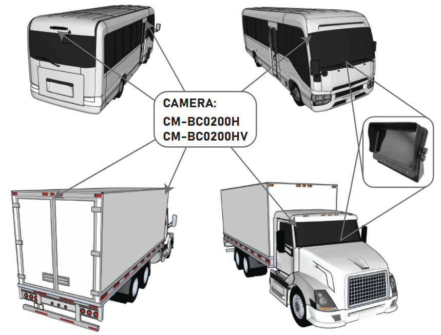
STEP 5: Connect your (CM-BC0200H / CM-BC0200HV) cameras to each of the individual AV connections (AV1, AV2, AV3, AV4). The monitor should show each camera in operation once connected. – refer to (pg.3) Wiring Diagram.
STEP 6: Connect the trigger wires appropriately to each operation on the vehicle. – refer to (pg.3) Wiring Diagram.
What is a TRIGGER WIRE?
A trigger wire when connected will take priority on the monitor when the associated vehicle function is triggered.
For example, if you connect (GREY) CAM 1 – TRIGGER WIRE to the vehicle’s backup function, CAMERA 1 – AV1 will take precedence when reversing, assuming you positioned this camera as the backup.
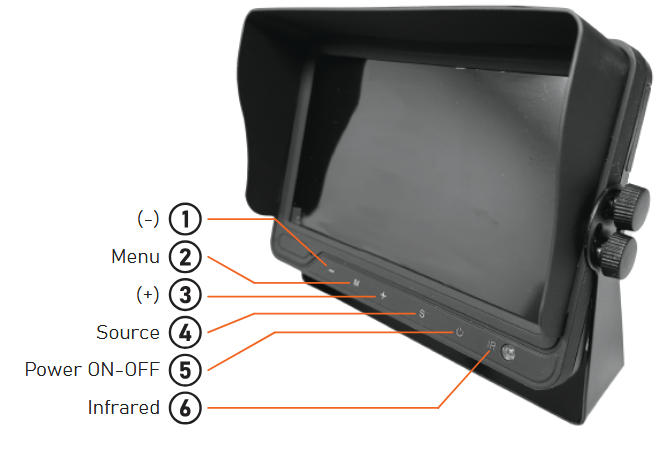
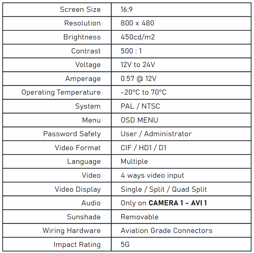
Monitor Specifications
Monitor Mounting Installation
STEP 1: Using M6 screws (x3), secure mounting bracket in desired location.
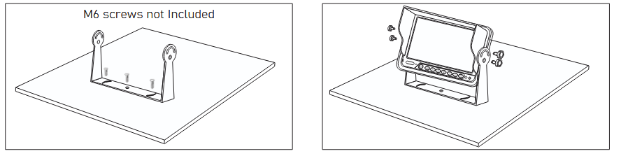
STEP 2: Place the monitor in between the bracket, adjust angle and tighten in place with bracket lock bolts provided.
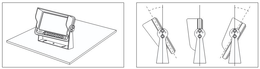
STEP 3: Adjust the angle up to 30° forward/backward for a suitable view.
Positioning
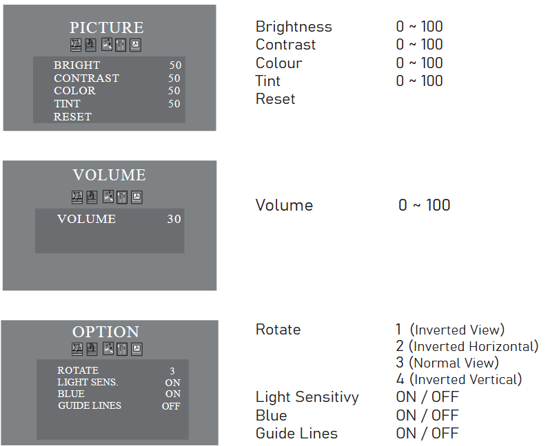
Menu Operation Instruction
REGULAR MENU
To access this menu, simply press ![]() on the remote control. The screen will show PICTURE.
on the remote control. The screen will show PICTURE.
Press![]()
![]() to select the attribute. Press
to select the attribute. Press ![]()
![]() to adjust the parameter.
to adjust the parameter.
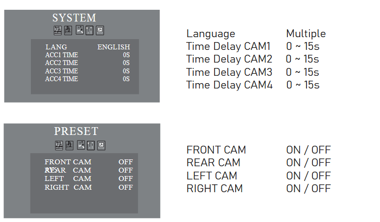
Pressing ![]() multiple times will switch between MENU options in succession as shown in the images below;
multiple times will switch between MENU options in succession as shown in the images below;
Troubleshooting
No Video On Monitor
There can be several factors as to why the Monitor does not display any video. Please check the following if this occurs;
- Verify that the camera is on the same camera input as shown on monitor. (eg. If monitor shows CH2, make sure the camera is connected to AV2)
- Could there be a bad connection somewhere?
– check that the harness is connected to the camera
– verify the trigger source is supplying power
–Diagnosis 1: connect any known working camera to the harness
–Diagnosis 2: swap out the harness with a known working harness
Video On Screen Is Choppy / Not Good / Blurry
This typically happens if the cable is loose, damaged or there may be some sort of electrical interference nearby;
- Ensure that the connections are tight from the monitor to harness and from harness to camera.
- Ensure cables are stored away from any possible electrical interference. (ie. radio devices, heavier cables, LED lights, switches, etc.)
- Try swapping out the camera with another camera if problem persists.
No Audio
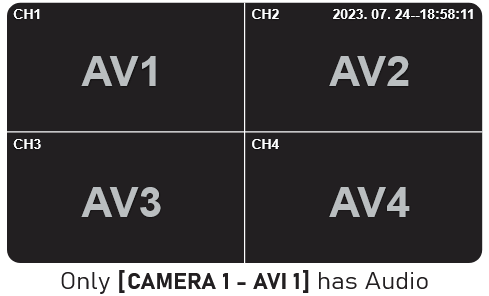
Make sure the camera with audio function is connected to AV1 (this is the only channel with sound support)
- Verify the volume setting is ON
- Verify the chosen camera has audio function