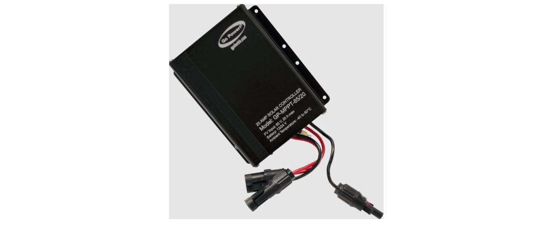
User Manual of Go Power GP-MPPT-85/20
MPPT Solar Controller
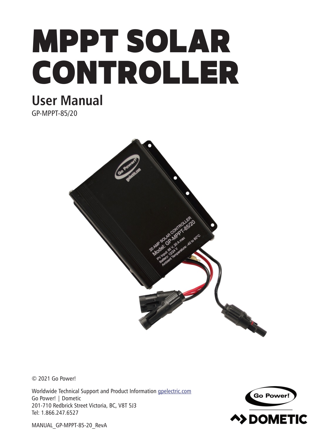
Congratulations on purchasing your Go Power! MPPT Solar Controller!
Record the unit’s model and serial number below. It is much easier and quicker to record this information now at the pre-installation stage.

![]() Product Packaging
Product Packaging
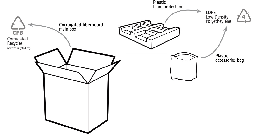
Please safely store the packing the IC Series was delivered in or recycle the packaging components as outlined below:
INSTALLATION OVERVIEW
1.1 INTRODUCTION
A Solar Controller (or Charge Controller / Regulator) is an essential component of your photovoltaic solar system. The Controller maintains the life of the battery by protecting it from overcharging. When your batteries have reached a 100% state of charge, the Controller prevents overcharging by limiting the current flowing into the batteries from your solar array.
The GP-MPPT-85/20 is a photovoltaic (PV) charge controller intended for use at 12 or 24 VDC system voltage and is rated for a nominal charge current of 20 amps.
The GP-MPPT-85/20 uses Maximum Power Point Tracking (MPPT) technology and a unique three stage charging algorithm.
The GP-MPPT-85/20 is suitable for use with lead acid batteries.
1.2 REGULATORY INFORMATION
![]()
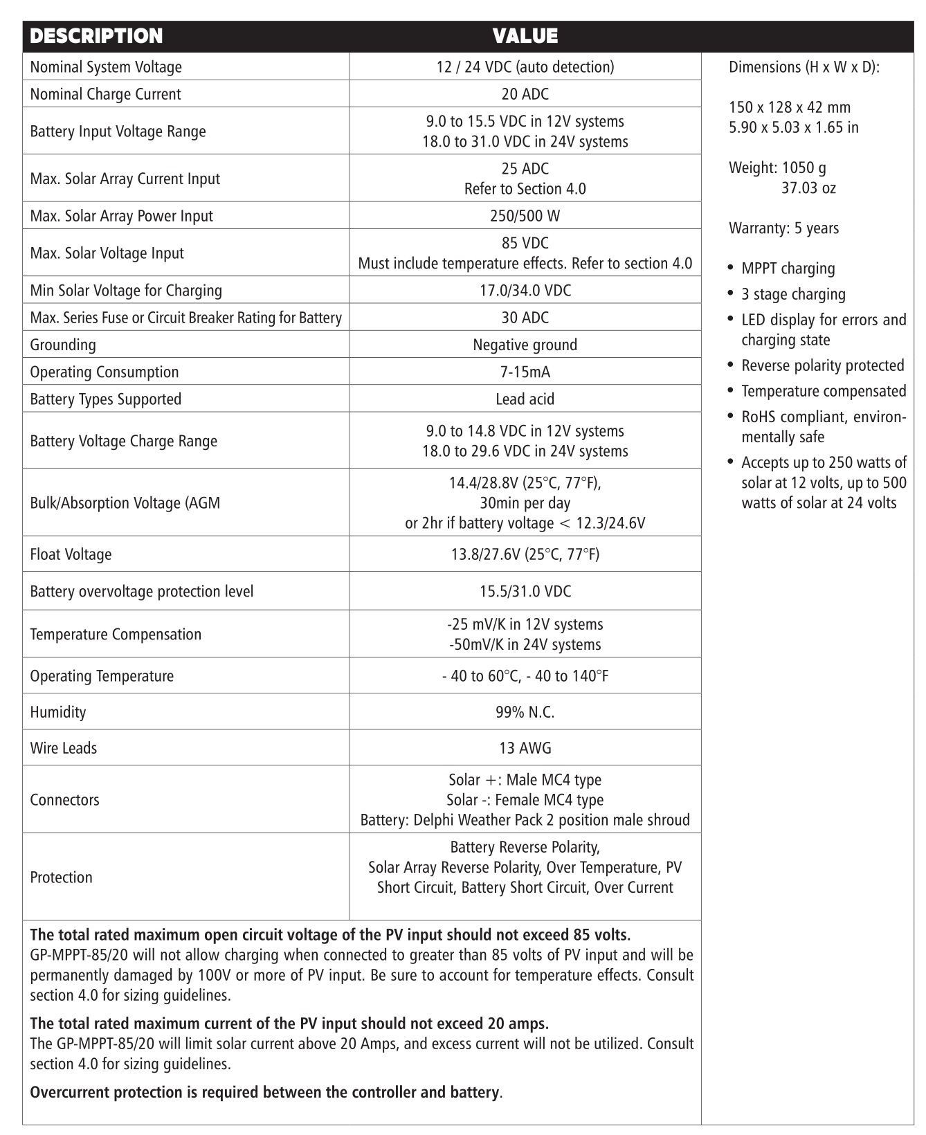
1.3 SPECIFICATIONS
IMPORTANT SAFETY INSTRUCTIONS
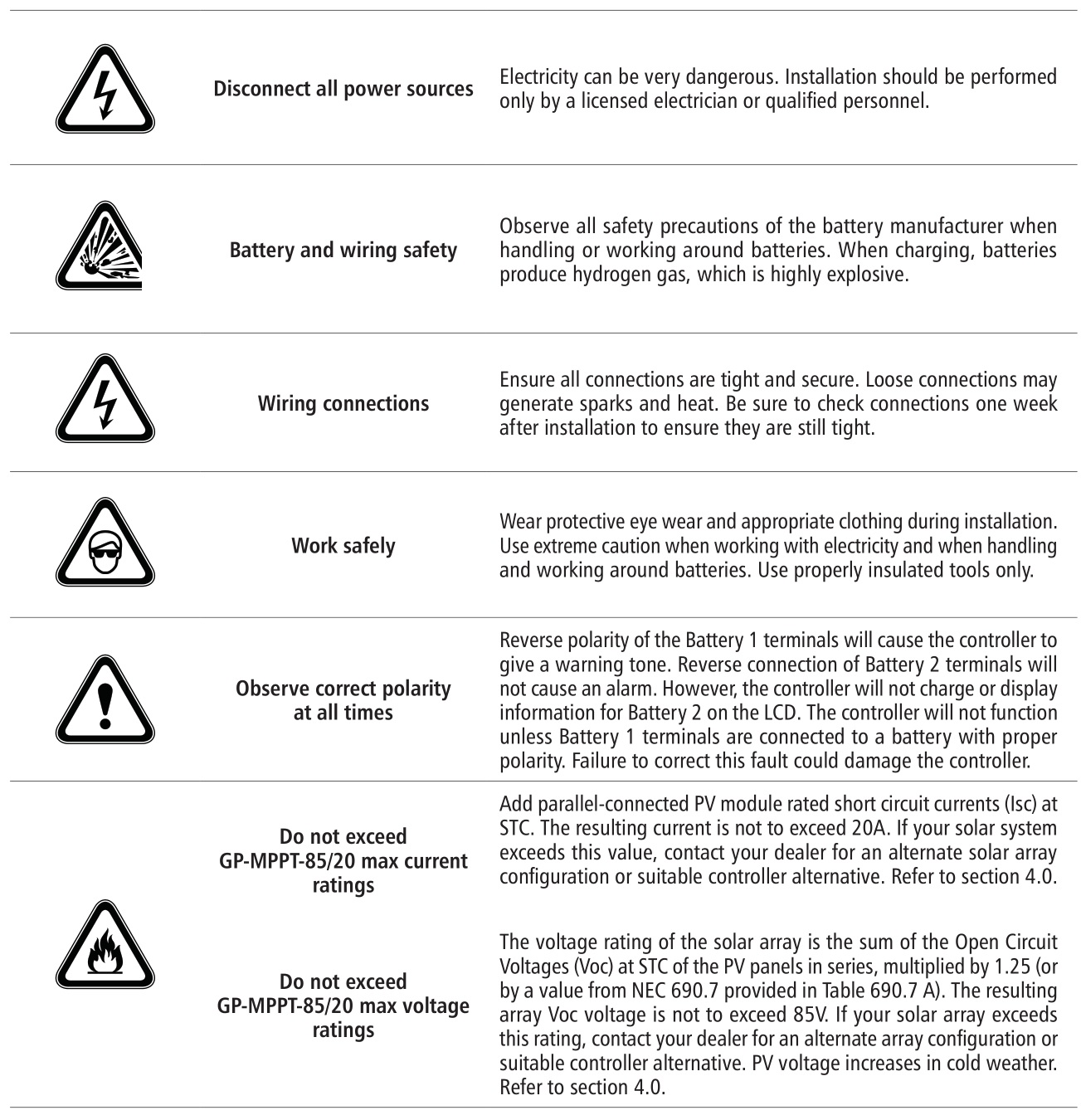
The GP-MPPT-85/20 is designed to be mounted vertically. Allow at least 2in (5cm) of space around GP-MPPT-85/20 for cooling.
Install on non-flammable surface. Do not install in direct sunlight.
The GP-MPPT-85/20 should be:
- Mounted as close to the battery as possible
- Mounted on a vertical surface to optimize cooling of the unit
- In an area with ventilation to dissipate hydrogen gas from batteries as well as heat from the controller
CHOOSING AN ARRAY
The panel voltage should not exceed 85V, or the controller will not charge the batteries. Panel voltage increases in cold weather compared to nameplate standard test condition (STC) ratings, so the highest panel array voltage must be calculated for the worstcase cold weather.
- Determine the worst-case cold temperature of the panel installation.
- Select the NEC temperature correction factor matching the worst-case cold temperature of the panel installation. Refer to table 690.7(A) of NEC 2017 or the latest version. When in doubt, select 1.25.
- Sum the open circuit voltages (Voc) of panels wired in series to obtain the array open circuit voltage at standard test conditions (STC).
- Multiply the array open circuit voltage by your selected NEC temperature correction factor, or multiply by 1.25 if you don’t know which factor to choose.
- The calculated value must be less than 85V. If not, select a different wiring configuration for the solar panels with fewer in series.
For example, the FLEX-100 has a Voc of 20.8V at STC. If four FLEX-100 solar panels were wired in series, then the array Voc would be 83.2V at STC. If the array were to be used in temperatures down to -40°C, then the NEC temperature correction factor would be 1.25. Multiplying the array Voc by 1.25 is 104V. This is greater than the allowed 85V, and the panels must be wired in a different configuration.
NEC 690.8 defines maximum solar current as the sum of parallel connected PV module short circuit currents (Isc) at STC multiplied by
1.25. This should not exceed 25A. Equivalently, the sum of the short circuit currents before the NEC factor is applied should not exceed the controller nominal current of 20A.
INSTALLATION
5.1 TOOLS AND MATERIALS NEEDED
- Philips Screwdriver (for mounting screws)
 If the GP-MPPT-85/20 Controller was purchased with a Go Power! RV Solar Power Kit then UV resistant wire is included. For instructions regarding the Go Power! RV Solar Power Kit installation, please refer to the Installation Guide provided with the Kit.
5.2 INSTRUCTIONS
- Complete the installation of the solar modules. If this GP-MPPT-85/20 was purchased as part of a Go Power! Solar Power Kit, follow the Installation Guide provided. Otherwise, follow manufacturer’s instructions for solar module mounting and wiring. Keep the solar array covered with an opaque material until all wiring is complete.
- Attach temperature sensor ring terminal to battery. Attach ring terminal to battery lug or use neoprene tape to attach ring terminal to battery case.
- Mount the GP-MPPT-85/20. Mount GP-MPPT-85/20 to a non-flammable surface. Mount vertically for proper heat dissipation.
- Select wire type and gauge. If this GP-MPPT-85/20 was purchased as part of a Go Power! Solar Power Kit, appropriate wire type, gauge and length is provided.
Wire type is recommended to be a stranded copper UV resistant wire. Wire fatigue and the likelihood of a loose connection are greatly reduced in stranded wire compared to solid wire. Wire gauge should be able to sustain rated current and minimize voltage drop.
WIRING DIAGRAM
![]() IMPORTANT: All wiring must be in accordance to National Electrical Code, ANSI/NFPA 70.
IMPORTANT: All wiring must be in accordance to National Electrical Code, ANSI/NFPA 70.
IMPORTANT: Identify the polarity (positive and negative) on the cable used for the battery and solar module. Use colored wires or mark the wire ends with tags. Although the GP-MPPT-85/20 is protected, reverse polarity contact may damage the unit.
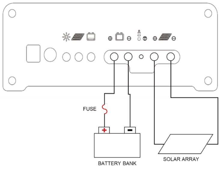
5. Complete battery wiring. Wire an appropriate fuse or breaker to the battery bank positive terminal. Wire the GP-MPPT-85/20 to the battery bank according to the wiring schematic in Section 6.0. Connect negative battery wire directly to the controller, not via the vehicle chassis. With battery power attached, the controller should power up and display LEDs.
Use of a positive or negative distribution bus is allowed between the controller and battery as long as it is properly sized, electrically safe and an adequate wire size is maintained.
![]() IMPORTANT: Always use appropriate circuit protection on any conductor attached to a battery.
IMPORTANT: Always use appropriate circuit protection on any conductor attached to a battery.
6. Complete solar wiring. Connect the solar wiring to the controller. Then remove the opaque material from the solar array. Connect negative solar array wire directly to the charge controller, not via the vehicle chassis.
Congratulations, your GP-MPPT-85/20 should now be operational. If the battery power is low and the solar array is producing power, your battery should begin to charge.
![]() WARNING: This unit is not provided with a GFDI device. This charge controller must be used with an external GFDI device as required by Article 690 of the National Electric Code for the installation location.
WARNING: This unit is not provided with a GFDI device. This charge controller must be used with an external GFDI device as required by Article 690 of the National Electric Code for the installation location.
WIRING DIAGRAM
![]() WARNING: When the photovoltaic (solar) array is exposed to light, it supplies a DC voltage to this equipment
WARNING: When the photovoltaic (solar) array is exposed to light, it supplies a DC voltage to this equipment
![]()
The fuse or breaker used should be no larger than 30A.
7.1 BATTERY CHARGING PROFILE CHART
![]()
Values before and after the slash correspond to 12 and 24 V systems respectively.

*When using Lithium batteries, the controller does not recognize the system voltage automatically. You will need to enter custom parameters.
View the complete manual at gpelectric.com/mppt-60-10 for instructions
7.2 LED DISPLAY
START UP
When GP-MPPT-85/20 is connected to the battery bank, the controller will start a power up mode which takes several seconds to complete.
LED INDICATORS
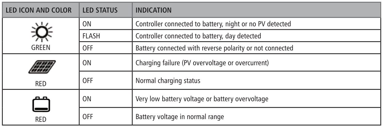
The green LED may flash for a few minutes after startup even if no PV is detected. This delay is to avoid erratic day/night transitions.
7.3 SWITCHING BETWEEN BATTERY BANKS
In some applications, two battery banks with different nominal voltages need charged from the same solar array. An external switch or relay can be used to select which battery bank is charged by the controller.
GP-MPPT-85/20 automatically determines nominal system voltage at startup. If there is a large jump in battery voltage (i.e. switching from one battery bank to another with a different nominal voltage), then the controller will detect the new nominal system voltage and reset.
![]() WARNING: Switching must be done with an external device. Each battery bank must have a fuse or breaker. The switching circuit must not allow the battery banks to be connected/shorted.
WARNING: Switching must be done with an external device. Each battery bank must have a fuse or breaker. The switching circuit must not allow the battery banks to be connected/shorted.
FREQUENTLY ASKED QUESTIONS
Before a problem is suspected with the system, read this section. There are numerous events that may appear as problems but
are in fact perfectly normal. Please visit gpelectric.com for the most up-to-date FAQs.
It seems like my flooded batteries are losing water over time.
Flooded batteries may need to have distilled water added periodically to replace fluid loss during charging. Excessive water loss during a short period of time indicates the possibility of overcharging or aging batteries.
When charging, my flooded batteries are emitting gas.
During charging, hydrogen gas is generated within the battery. The gas bubbles stir the battery acid, allowing it to receive a fuller state of charge.
![]() IMPORTANT: Ensure batteries are in a well-ventilated space.
IMPORTANT: Ensure batteries are in a well-ventilated space.
TROUBLESHOOTING PROBLEMS
How to Read this Section
Troubleshooting Problems is split into four sub-sections, grouped by symptoms involving key components. Components considered irrelevant in a diagnosis are denoted ‘Not Applicable’ (N/A). A multimeter or voltmeter may be required for some procedures listed.
Check the controller LED display as the first step.
![]()
It is imperative all electrical precautions stated in the Safety Instructions and outlined in the Installation Section are followed. Even if it appears the system is not functioning, it should be treated as a fully functioning system generating live power.
9.1 BLANK LED DISPLAY
Display Reading: Blank (no LEDs)
Time of Day: Daytime/Nighttime
Possible Causes:
Battery voltage or connection, blown fuse/breaker, wiring/connector problems
How to tell:
- Check the battery voltage. If battery voltage is <9V, the controller will not charge, and the LEDs may not function correctly.
- Check wiring polarity.
- Check all fuses/breakers, wires, and connections. A blown fuse/breaker, damaged wire, or loose connection will prevent battery power from reaching the controller.
Remedy:
- Use an external charging source to charge the battery voltage above 9V. Consider battery replacement.
- Correct any reverse polarity connections.
- Check that all connections are clean, tight, and secure. Check that all wires and insulation are intact. Check for possible shorts or damaged equipment. Replace blown fuses or reset breakers.
9.2 RED BATTERY LED ON
Display Reading: Red battery LED on
Time of Day: Daytime/Nighttime
Possible Cause:
- Battery voltage is too low because of excessive voltage drop from battery bank to controller or insufficient solar power.
- Battery voltage is too low because of excessive load power draw from battery bank.
- Battery voltage is too high because of secondary charging source.
- Battery voltage is too high because of a short.
How to tell:
Check the battery bank voltage with a voltmeter. Less than 11.9/23.8V is a low battery voltage. Above 15.5/31.0V is a high battery voltage.
Check the battery voltage when loads are on and recheck when loads are off. If there is a voltage discrepancy of more than 1V, the loads may be too large.
Remedy:
- Check all wiring and connections from the controller to the battery bank. Ensure that all connections are clean, tight, and secure. Shorten the distance from the controller to battery bank or obtain larger wire. It is also possible to double up the existing gauge wire (i.e. two wire runs) to simulate a larger wire. Wait for system to charge battery. Turn off loads for faster charging.
- Increase the battery bank capacity. Consult your dealer or installer for assistance.
- Remove any secondary charging source. GP-MPPT-85/20 will only begin charging after battery voltage has fallen to a normal level. Use a voltmeter to check if voltages are in correct range.
- De-energize system and disconnect equipment. Use a DMM with a connectivity setting to check for shorts in wiring or equipment. Otherwise, use a voltmeter to check if voltages are in correct range.
9.3 RED SOLAR LED ON
Display Reading: Red solar LED on
Time of Day: Daytime/Nighttime
Possible Cause:
- PV array voltage is greater than 85V.
- PV array current is greater than 20A.
How to tell:
Measure PV array voltage. If it’s greater than 85V, the controller will not charge.
Check PV module nameplate for ratings.
Remedy:
Change PV array wiring configuration. Consult your dealer or installer for assistance.
9.4 PROBLEMS WITH CHARGING
Problem: Controller doesn’t seem to be charging
Time of Day: Daytime, clear sunny skies
Possible Cause:
Current is being limited as per normal operation or poor connection between solar array and controller.
How to tell:
The green LED will flash if controller is charging. The green LED is on continuously if controller isn’t charging or if there’s insufficient solar voltage.
With the solar array in sunlight, check the voltage of the solar array terminals with a voltmeter.
Remedy:
Check all connections from the controller to the array including checking for correct wire polarity. Check that all connections are clean, tight, and secure.
Wait 5 minutes and recheck charging status. A delay is present to prevent erratic behavior.
Problem: Charge current is less than expected
Time of Day: Daytime, clear sunny skies
Possible Causes:
- Current is being limited as per normal operation.
- Incorrect series/parallel configuration and/or wiring connections and/or wire gauge.
- Dirty or shaded module or lack of sun.
- Blown diode in solar module when two or more modules are connected in parallel.
How to tell:
- Check battery voltage. If battery has reached the target charge voltage, then current is being limited per normal operation.
- Check the heatsink temperature. Controller will limit charge current when internal temperatures are too high.
- Check that the modules and batteries are configured correctly. Check all wiring connections.
- Modules look dirty, overhead object is shading modules or it is an overcast day in which a shadow cannot be cast.
Avoid any shading no matter how small. An object as small as a broomstick held across the solar module may cause the power output to be reduced. Overcast days may also cut the power output of the module.
Remedy:
Reconnect in correct configuration. Tighten all connections. Check wire gauge and length of wire run.
Clean modules, clear obstruction or wait for conditions to clear.
If the open circuit voltage of a module is lower than the manufacturer’s specifications, the module may be faulty. Check for blown diodes in the solar module junction box which may be shorting the power output of module.
Go Power! warrants the GP-MPPT-85/20 for a period of five (5) years from the date of shipment from its factory. This warranty is valid against defects in materials and workmanship for the five (5) year warranty period. It is not valid against defects resulting from, but not limited to:
- Misuse and/or abuse, neglect, or accident
- Exceeding the unit’s design limits
- Improper installation, including, but not limited to, improper environmental protection and improper hook-up
- Acts of God, including lightning, floods, earthquakes, fire, and high winds
- Damage in handling, including damage encountered during shipment
This warranty shall be considered void if the warranted product is in any way opened or altered. The warranty will be void if any eyelet, rivets, or other fasteners used to seal the unit are removed or altered, or if the unit’s serial number is in any way removed, altered, replaced, defaced, or rendered illegible.
10.1 REPAIR AND RETURN INFORMATION
Visit www.gpelectric.com to read the “frequently asked questions” section of our website to troubleshoot the problem. If trouble persists:
- Call your Go Power!® Technical Support team (1-866-247-6527).
- Return defective product to place of purchase.
© 2021 Go Power!
Worldwide Technical Support and Product Information gpelectric.com
Go Power! | Dometic
201-710 Redbrick Street Victoria, BC, V8T 5J3
Tel: 1.866.247.6527
MANUAL_GP-MPPT-85-20_RevA

