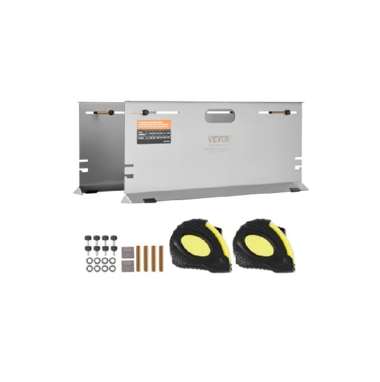
VEVOR WBS-011 Wheel Alignment System Instruction Manual


Model:WBS-011
This is the original instruction, please read all manual instructions carefully before operating. VEVOR reserves a clear interpretation of our user manual. The appearance of the product shall be subject to the product you received. Please forgive us that we won’t inform you again if there are any technology or software updates on our product.
IMPORTANT SAFEGUARDS
 WARNING: Read and understand this entire manual before operating or servicing this product. Failure to follow these warnings and instructions can cause personal injury or damage to valuable property.
- The product complies with relevant standards and regulations.Installation of this device must comply with all applicable regulations, and it should only be operated in well-ventilated areas. Please read the user manual before installing and using this equipment.
- This appliance is not intended for use by persons (including children) with reduced physical, sensory or mental capabilities, or lack of experience and knowledge, unless they have been given supervision or instruction concerning use of the appliance by a person responsible for their safety.
- Children shall not play with the appliance.
- Please properly keep product. Check whether the product is abnormal before use. If it is abnormal, please stop using it.
- Please use the product according to the intended use, warn of potential injury from misuse.
ASSEMBLY PRECAUTIONS
- Assemble only according to these instructions. Improper assembly can create hazards.
- Wear ANSI-approved safety goggles and heavy-duty work gloves during assembly.
- Keep assembly area clean and well-lit.
- Keep bystanders out of the area during assembly.
- Do not assemble when tired or when under the influence of alcohol, drugs or medication.
- Caution with the risks of pinching or cuts during assembly.
- Product capabilities apply to properly and completely assembled product only.
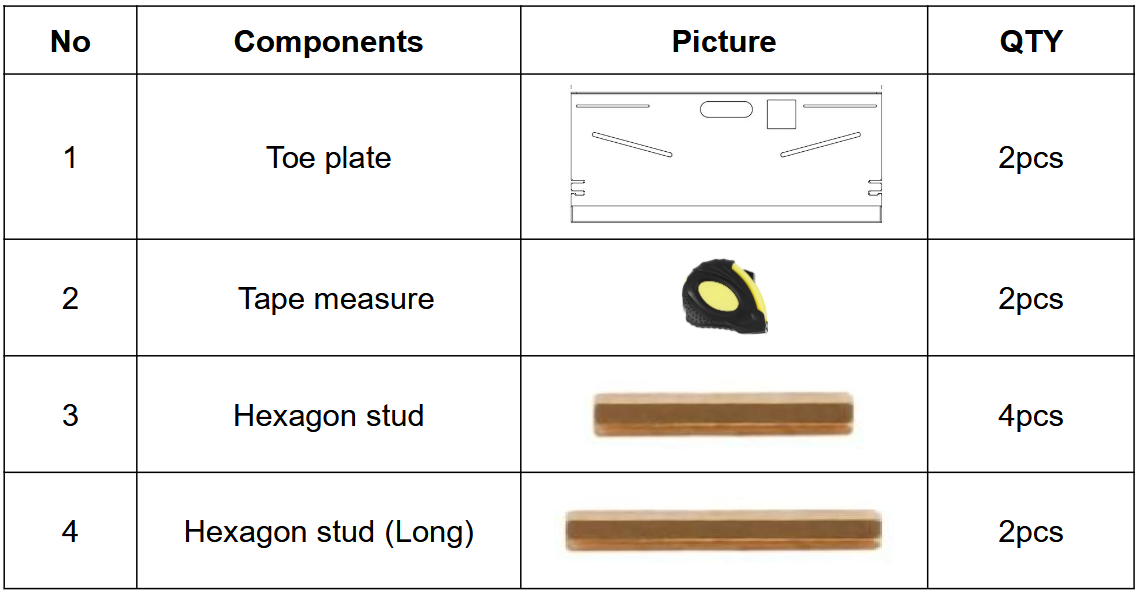
- or additional information regarding the parts listed in the following pages, please refer to the Assembly Diagram of this manual. Unwrap and separate all parts in a clean work area. Please keep small spare parts out of children’s reach.
SAVE THESE INSTRUCTIONS
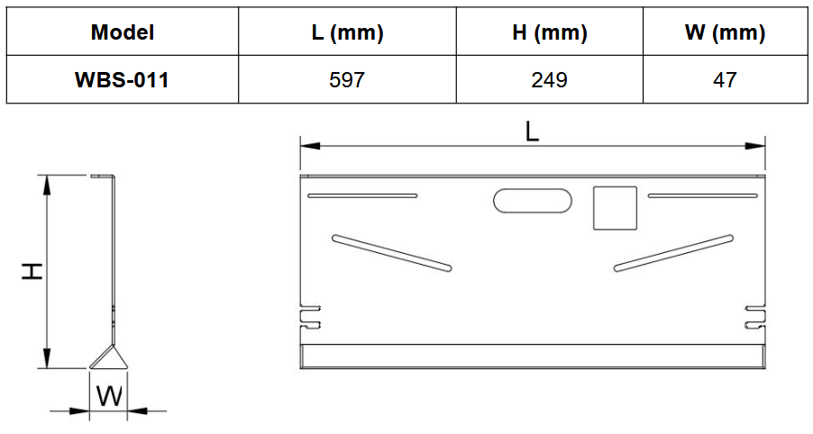
PRODUCT SPECIFICATIONS:
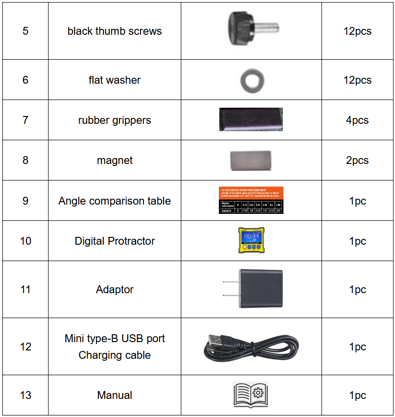
SIMPLE INSTRUCTION
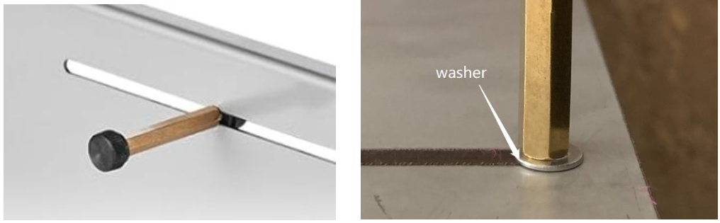
Step 1: Install support studs.
Use the 12 thumb screws to attach them to the plates as desired. Place 8 flat pads on the thumb screw and prop screw sides as shown,

Step 2: Bolt on the upper contact point.
One washer sits between the chassis of the gauge and the threaded shaft. The small backing plate threads on the backside . To adjust the position of the contact point only the threaded shaft needs to be turned, the chassis of the gauge will prevent the backing plate from turning.
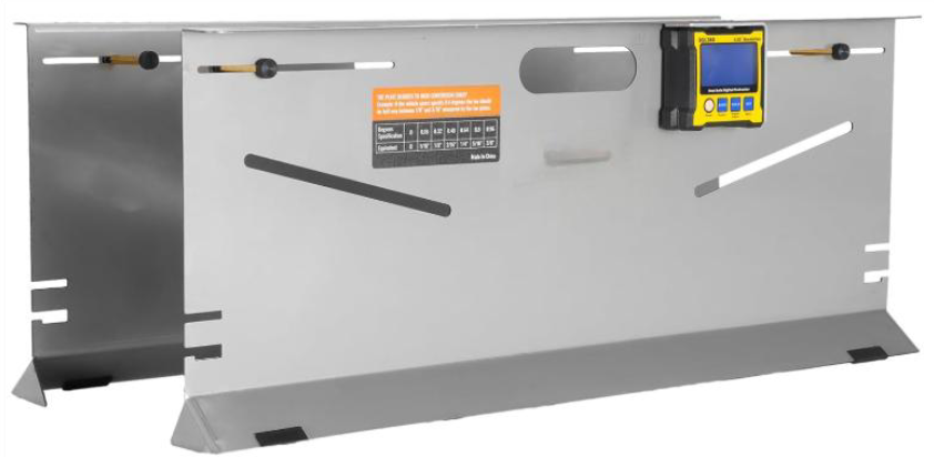
Step 3: Attach the digital protractor to the mounting surface of the toe plate
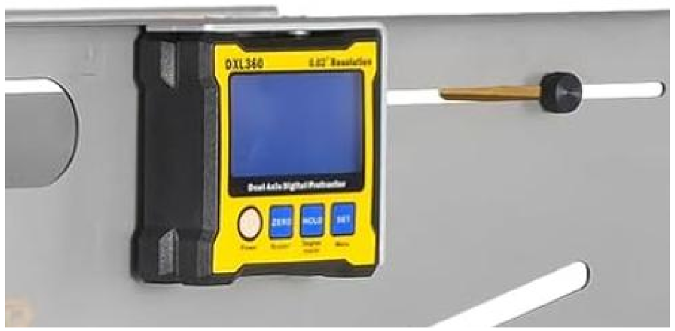
Assembly should now be complete.
Automotive Caster Measurement Instructions
Method 1: True Value Caster Measurement
Step 1 a: Create Reference Line
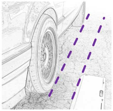
Center the steering wheel. Lay the plain toe plate (plate without the Digital Protractor) down on the ground approximately 8” from the tire. The bottom of the plate should be pointing toward the vehicle.
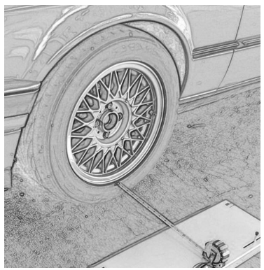
Step 1 b: Align the angle of the reference plate.
Visually align the edge of the plate so it’s approximately parallel to the side of the vehicle, a indicated by the red line. This can be approximated as the precision of this will not affect the accuracy of the caster measurement.
Step 2: Turn the wheel being measured inwards
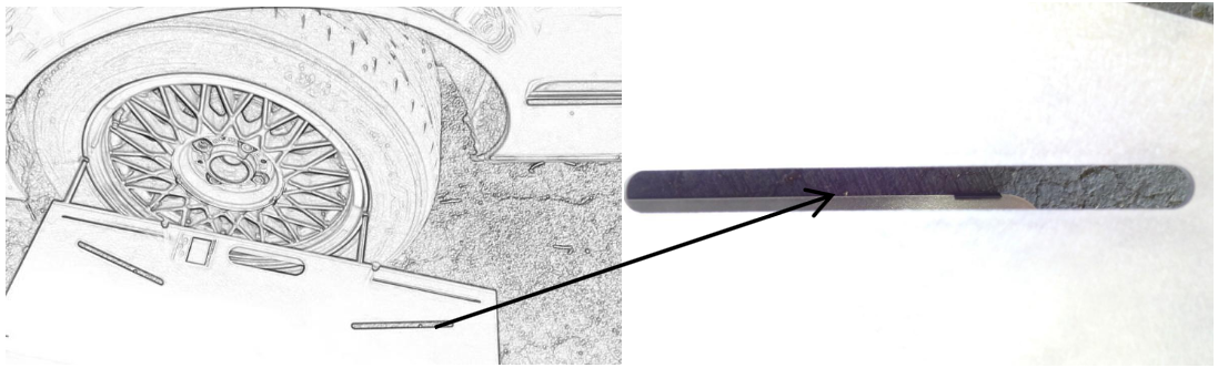
Turn the steering wheel so the front of the wheel being measured is pointing inwards. Hold the camber plate sideways to the wheel, with the caster sight hole toward the rear of the vehicle. Use the caster hole to check the angle of the wheel. Adjust the angle of the wheel as needed until the edge of the caster sight is parallel to the reference plate.
Step 3: Zero the digital readout
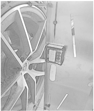
When the angle has been set, hold the camber plate to the wheel in the camber measuring orientation, then power on the digital readout and zero it. Do not turn off the digital readout.
Step 4: Turn the whee outwards
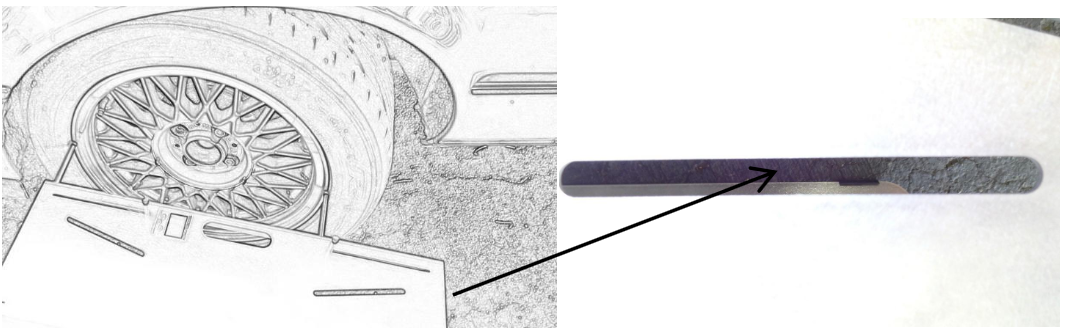
Turn the steering wheel so the front of the wheel being measured is pointing outwards. Hold the camber plate to the wheel, with the caster sight hole toward the front of the vehicle. Use the caster sight to check the angle of the wheel. Adjust the angle of the wheel as needed until the edge of the caster sight is parallel to the reference plate.
Step 5: Calculate Caster
Place the camber plate on the wheel as you would to measure camber, and note the value. To calculate caster multiply the camber value displayed by 2. The result is the caster measurement. For example the digital readout is displaying 4.25, so the caster is 4.25*2= 8.5 degrees
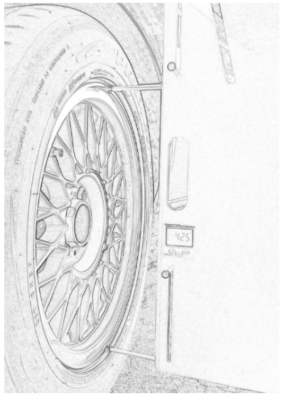
Repeat the process on the other front wheel as desired.
Method 2: Caster Comparison
Step 1:
Turn the steering wheel 1 turn from center. Place the camber gauge on the wheel as you would to measure camber and zero the digital readout.
Step 2:
Turn the steering wheel 1 turn from center the opposite direction. Place the the camber gauge on the wheel and note the value displayed on the digital readout. Repeat on the other front wheel.
Step 3:
Compare the two measurements. Again this is not the real caster reading itself, but quick and easy way to compare the side to side caster values. The two values should be approximately equal.
Automotive Camber Measurement Instructions
Calibration
The digital readout auto-levels when it is powered on. If the working surface is not level the readout can be calibrated.
IMPORTANT!!!: The digital readout must always face the same direction it was facing when calibrated. If the readout is forward (toward the front of the car) when it is calibrated the readout should be facing forward when camber is measured on both sides of the vehicle. This will keep the calibration.
Step 1: Calibration (if necessary)
Adjust the sliding contact point to the end of the toe plate, and orient it so the two contact points are sitting on the ground (as shown below). Rotate the digital readout so it is upright, power it on, and press the zero button on the gauge to calibrate.
Caution:If the surface is very wavy or bumpy the calibration may still not be perfect. In this case a long,straight piece of metal or similar can be laid down and used to calibrate the digital readout.
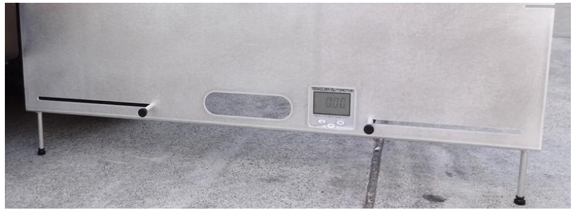
Tip: If it is desired to simply add a certain amount of camber, the gauge can also be calibrated on the wheel itself. For example if you are out at the track and decide you want to add 1 degree more negative camber, the gauge can be placed on the wheel and zeroed. Now camber can be adjusted until the gauge reads 1 degrees negative camber.
Step 2: Measure Camber
Adjust the upper contact point so that both contact points touch the wheel rim. The camber value will instantly be displayed on the digital readout. Remember that the readout must always face the same direction it was facing when calibrated (meaning it will have to be turned around the toe plate when measuring the other side of the vehicle).
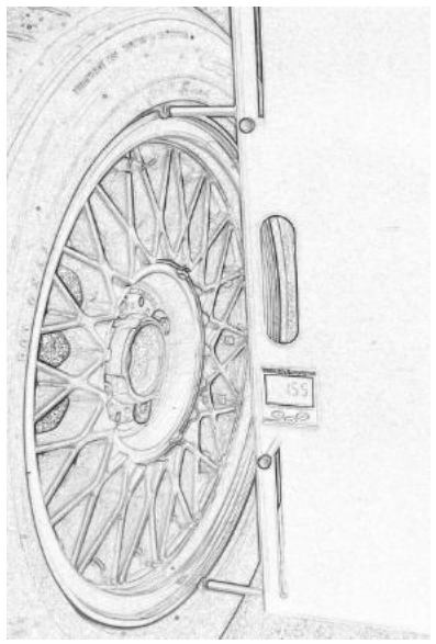
Caution: The digital readout is very sensitive, so sensitive that you may make yourself crazy trying to adjust to the exact desired value. Alignment specs given by manufactures typically have a camber error range of plus/minus 0.1 degrees, meaning if the camber is within 0.1 degrees of the desired value the car is considered to be within spec. Keep this in mind while adjusting camber, if camber is a coupe tenths off the exact desired value, there will be no perceivable difference in handling or tire wear.
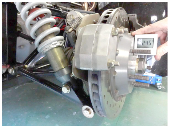
Tip: If the suspension the vehicle must be disassembled to adjust camber (threaded ball-joints, rod ends, etc.), it is possible to speed up the process using the digital readout on the wheel hub or brake disk. First measure the camber as normal, and determine how much you want to add or subtract. Then after jacking up the vehicle use the digital readout on the hub. This will NOT provide an accurate camber measurement because the suspension is unloaded, but it can provide an accurate camber change measurement. Meaning if you change the angle of the hub by one degree, the camber should also change by about 1 degree. This will eliminate having to repeatedly disassemble/reassemble the suspension to guess and check. Do not zero the digital readout on the hub unless you want to loose your calibration.
Toe Plates Toe Measurement Instructions
The rim stand-offs work on nearly all cars and suv’s, however it is possible that the sidewall on some trucks and suv’s may be too tall for the stand-offs to properly contact the wheel rim. In this case either the stand-offs can be removed and the plates can be used as standard toe plates (placed flat against the tire). Or you can use two pads of the same height and place under the plates to raise them up higher.
Before you start ensure the vehicle’s steering wheel is centered. If they vehicle is equipped with hub caps they will either need to be removed.
Step 1: Adjust flat slot plate
Place the toe plate with the straight tape measure slots close to the wheel, so that when the stand-offs are resting against the rim, the plate will be sitting vertical. Use the notch cut into the top edge of the plate to center the plate on the wheel.
Use the thumb screws to adjust the stand-offs so they will contact the rim of the wheel. When tightening is it not necessary to use two hands, simply apply some pressure to the plate.
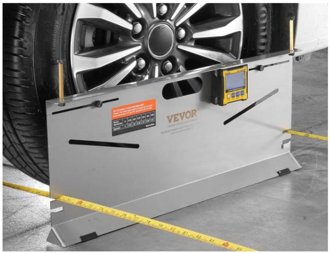
Step 2: Extend tape measures
Run the tape measures underneath the car as shown, 80 inches should be enough.
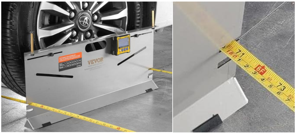
Step 3: Adjust stand-offs
Use the same procedure as shown in step 1 to fit the other toe plate on the opposite side of the vehicle and place the tape measures into the tape holder slots.
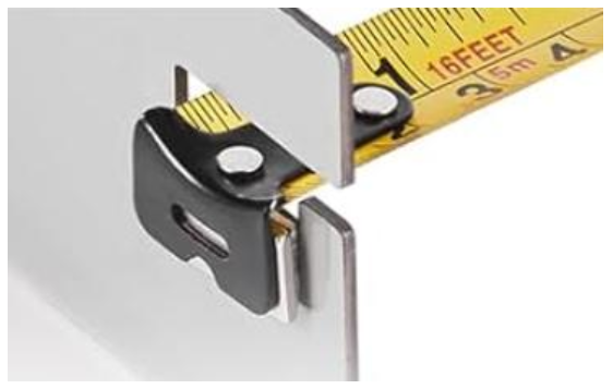
Caution:Check that the stand-offs on both plates are properly seated against the rim of the wheel.
Step 4: Measure Toe
Unlock the tape measures and slide them into the slots. Do NOT re-lock the tape measures.
Leaving them unlocked will apply the proper amount of tension. Pull on them slightly and note the measurements.
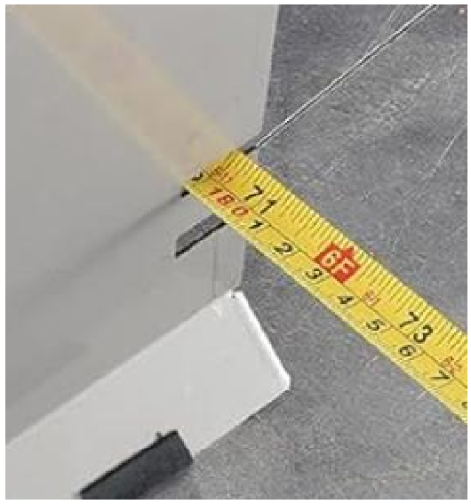
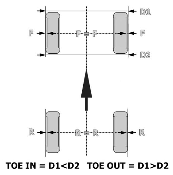
The rear tape measurement (side towards the rear of the vehicle) minus the front tape measurement(side closest to the front of the vehicle) is the total toe of the axle. A larger measurement on the front side indicates toe out, and a larger
measurement on the rear side indicates toe in. For example, if the front measurement D1 is 66” and the rear measurement D2 is 66 3/32 the axle has a total toe in of 3/32” .
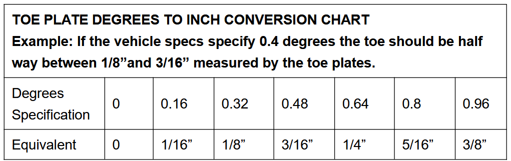
Note: When using alignment specs, note that the toe plates measure the TOTAL toe, not the toe of each wheel. Thus if your specs are given for each wheel you will need to add those values together.
For example, if the toe in of each wheel is suppose to be 0.15 degrees, then the total toe should be 0.15+0.15= 0.3 degrees.
The optional alignment specs gives total toe so these specs do not need modification, however you should use the degree specifications, NOT the inch specifications.
Tip: if the toe is correct but the steering wheel is crooked, turn the tire rod on one side in, and the tie rod on the other side out an equal number of turns. This will keep the toe measurement but adjust the position of the steering wheel. Make sure to adjust it the right direction!